Hydraulic Operation -
Flow Control Adjustment
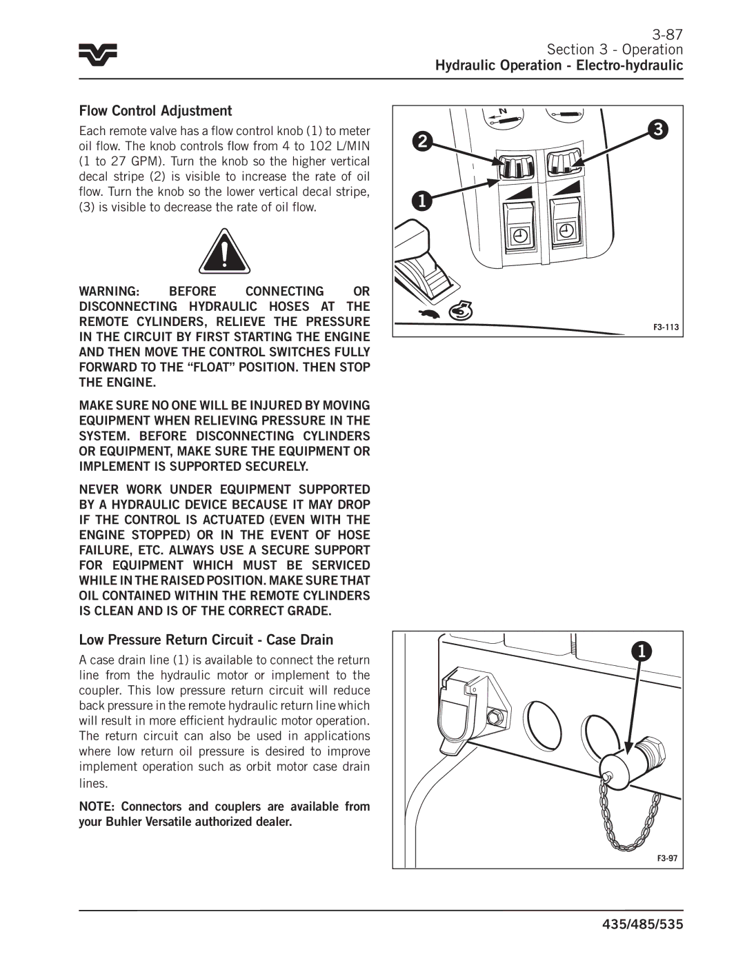
Each remote valve has a flow control knob (1) to meter oil flow.. The knob controls flow from 4 to 102 L/MIN (1 to 27 GPM).. Turn the knob so the higher vertical decal stripe (2) is visible to increase the rate of oil flow.. Turn the knob so the lower vertical decal stripe,
(3) is visible to decrease the rate of oil flow..
WARNING: Before connecting or disconnecting hydraulic hoses at the remote cylinders, relieve the pressure in the circuit by first starting the engine and then move the control switches fully forward to the “float” position. Then stop the engine.
Make sure no one will be injured by moving equipment when relieving pressure in the system. Before disconnecting cylinders or equipment, make sure the equipment or implement is supported securely.
Never work under equipment supported by a hydraulic device because it may drop if the control is actuated (even with the engine stopped) or in the event of hose failure, etc. always use a secure support for equipment which must be serviced while in the raised position. Make sure that oil contained within the remote cylinders is clean and is of the correct grade.
2 | 3 |
| |
1 |
|
|
Low Pressure Return Circuit - Case Drain
A case drain line (1) is available to connect the return line from the hydraulic motor or implement to the coupler.. This low pressure return circuit will reduce back pressure in the remote hydraulic return line which will result in more efficient hydraulic motor operation.. The return circuit can also be used in applications where low return oil pressure is desired to improve implement operation such as orbit motor case drain
lines..
NOTE: Connectors and couplers are available from your Buhler Versatile authorized dealer.
1 |
435/485/535 |