3-25 Section 3 - Operation
Electronic Instrument Cluster - EIC
Electronic Instrument Cluster
7 |
| 1 | 2 | 3 |
|
|
|
| 4 |
|
|
|
| |
6 | 2 | 2 |
| 5 |
Introduction |
|
|
|
|
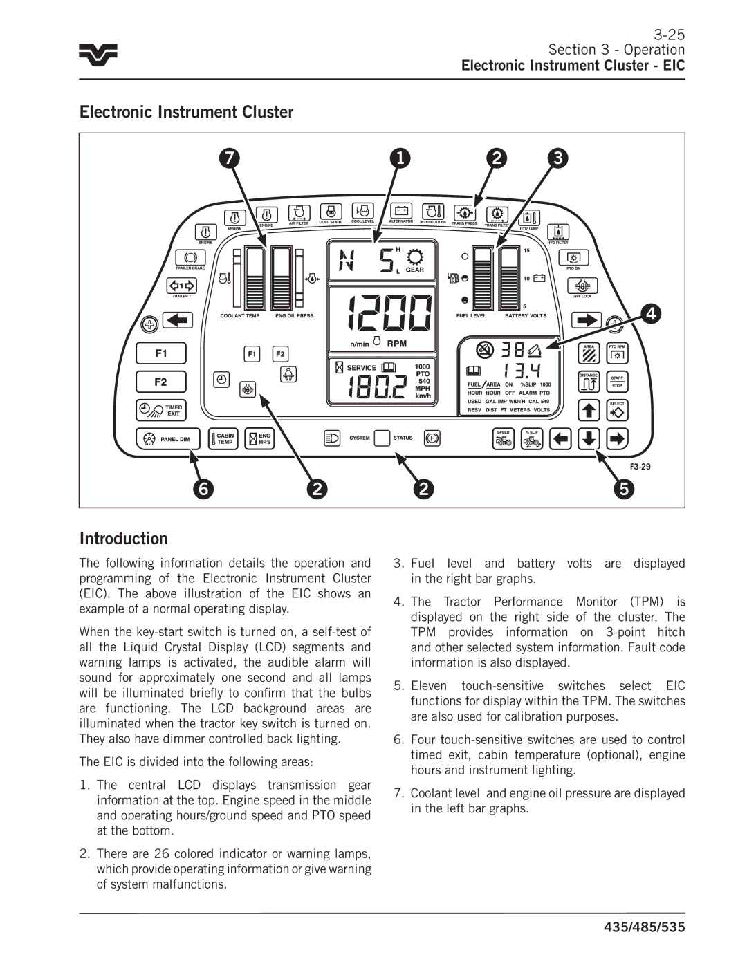
The following information details the operation and programming of the Electronic Instrument Cluster (EIC).. The above illustration of the EIC shows an example of a normal operating display..
When the
The EIC is divided into the following areas:
1.The central LCD displays transmission gear information at the top.. Engine speed in the middle and operating hours/ground speed and PTO speed at the bottom..
2.There are 26 colored indicator or warning lamps, which provide operating information or give warning of system malfunctions..
3. Fuel level and battery volts are displayed in the right bar graphs..
4.The Tractor Performance Monitor (TPM) is displayed on the right side of the cluster.. The TPM provides information on
5..Eleven
6.Four
7.Coolant level and engine oil pressure are displayed in the left bar graphs..