Section 3 - Operation
Hydraulic Operation - Manual
Remote Control Valve Operation - Manual
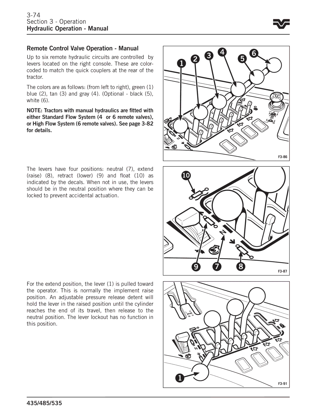
Up to six remote hydraulic circuits are controlled by levers located on the right console.. These are color- coded to match the quick couplers at the rear of the tractor..
The colors are as follows: (from left to right), green (1) blue (2), tan (3) and gray (4).. (Optional - black (5), white (6)..
NOTE: Tractors with manual hydraulics are fitted with either Standard Flow System (4 or 6 remote valves), or High Flow System (6 remote valves). See page
The levers have four positions: neutral (7), extend (raise) (8), retract (lower) (9) and float (10) as indicated by the decals.. When not in use, the levers should be in the neutral position where they can be locked to prevent accidental actuation..
For the extend position, the lever (1) is pulled toward the operator.. This is normally the implement raise position.. An adjustable pressure release detent will hold the lever in the raised position until the cylinder reaches the end of its travel, then release to the neutral position.. The lever lockout has no function in this position..
|
| 2 | 3 | 4 | 5 | 6 |
1 |
|
|
| |||
|
|
|
| |||
|
|
|
|
|
| |
|
|
|
|
|
| ON |
|
|
|
|
|
| STOP |
N |
|
|
|
|
|
|
|
|
|
|
|
|
|
10 |
|
|
|
|
| |
|
| 9 |
| 7 | 8 | |
|
|
|
|
|
| |
L | H |
|
|
|
|
|
N |
|
|
|
|
| |
| R |
|
|
|
| |
| M |
|
|
|
| |
|
|
|
|
|
| |
|
| N |
|
|
|
|
1 |
|
|
|
|
| |
|
|
|
|
|
| |