3-43 Section 3 - Operation
EIC - Calibration
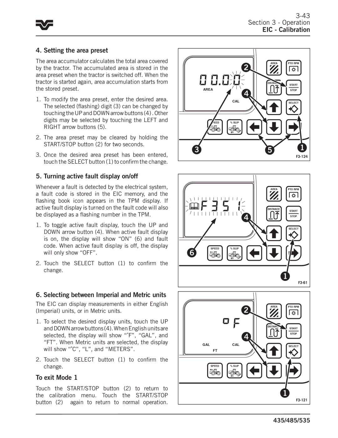
4. Setting the area preset
The area accumulator calculates the total area covered by the tractor.. The accumulated area is stored in the area preset when the tractor is switched off.. When the tractor is started again, area accumulation starts from the stored preset..
1.To modify the area preset, enter the desired area.. The selected (flashing) digit (3) can be changed by touching the UP and DOWN arrow buttons (4) .. Other digits may be selected by touching the LEFT and RIGHT arrow buttons (5)..
2.The area preset may be cleared by holding the START/STOP button (2) for two seconds..
3.Once the desired area preset has been entered, touch the SELECT button (1) to confirm the change..
5. Turning active fault display on/off
Whenever a fault is detected by the electrical system, a fault code is stored in the EIC memory, and the flashing book icon appears in the TPM display.. If active fault display is turned on the fault code will also be displayed as a flashing number in the TPM..
1.To toggle active fault display, touch the UP and DOWN arrow button (4).. When active fault display is on, the display will show “ON” (6) and fault code.. When active fault display is off, the display will only show “OFF”..
2.Touch the SELECT button (1) to confirm the change..
6. Selecting between Imperial and Metric units
The EIC can display measurements in either English (Imperial) units, or in Metric units..
1.To select the desired display units, touch the UP and DOWN arrow buttons (4).. When English units are selected, the display will show “˚F”, “GAL”, and “FT”.. When Metric units are selected, the display will show “˚C”, “L”, and “METERS”..
2.Touch the SELECT button (1) to confirm the change..
To exit Mode 1
Touch the START/STOP button (2) to return to the calibration menu.. Touch the START/STOP button (2) again to return to normal operation..
|
| 2 | AREA | PTO RPM |
|
|
|
| |
|
|
| DISTANCE | START |
|
|
|
| |
| AREA | 4 |
| STOP |
|
|
|
| |
|
| CAL |
| SELECT |
| SPEED | % SLIP |
|
|
| 3 |
| 5 | 1 |
|
|
|
| |
|
|
| AREA | PTO RPM |
|
|
| DISTANCE | START |
|
| 4 |
| |
|
|
| STOP | |
|
|
|
| |
|
|
|
| SELECT |
6 | SPEED | % SLIP |
|
|
|
|
|
| |
|
|
|
| 1 |
|
|
|
| |
|
| 2 | AREA | PTO RPM |
|
|
|
| |
|
|
| DISTANCE | START |
|
|
|
| |
|
| 4 |
| STOP |
|
|
|
| |
| GAL | CAL |
| SELECT |
| FT |
|
|
|
| SPEED | % SLIP |
|
|
|
|
|
| 1 |
|
|
|
| |
|
|
| 435/485/535 | |