Americas Headquarters
Text Part Number OL-20862-01
Page
N T E N T S
Iii
Manager
Key Expansion Module Settings on the Phone
Interacting with Cisco Unified Wireless APs
Configuring Personal Directory
Vii
Status Menu
Viii
Technical Specifications
Installing the Wall Mount for the Cisco Unified IP Phone E-1
Organization
Overview
Audience
Chapter Description
Xii
Cisco Unified IP Phones 8961, 9951,
Related Documentation
Cisco Product Security Overview
Xiii
Boldface font
Document Conventions
Convention Description
Xiv
An Overview of the Cisco Unified IP Phone
1shows the main components of the Cisco Unified IP Phone
1describes the buttons on the Cisco Unified IP Phone
Features on the Cisco Unified IP Phone
2shows the main components of the Cisco Unified IP Phone
2describes the buttons on the Cisco Unified IP Phone
Features on the Cisco Unified IP Phone
3shows the main components of the Cisco Unified IP Phone
3describes the buttons on the Cisco Unified IP Phone
Features on the Cisco Unified IP Phone
Communications Manager System Guide
What Networking Protocols are Used?
Networking Protocol Purpose Usage Notes
Authentication on Cisco Unified IP Phones section
URL
Nologieswhitepaper0900aecd804cd46d.shtml
See the LLDP-MED and Cisco Discovery Protocol
White paper
SIP
System Guide
Feature Overview
Cisco Unified Communications Manager
UDP
Configuring Telephony Features
Related Topic
Topic Reference
Providing Users with Feature Information
See the Overview of Supported Security Features section on
See the Security Restrictions section on
Manager
Overview of Supported Security Features
Unified Communications Manager Security Guide
IP Phone section on page 3-21for more information
Choose Administrator
Feature Description
Cisco Unified Communications Manager Security Guide
Phones section on page 1-22for more information
Understanding Security Profiles
Identifying Secure Encrypted Phone Calls
Establishing and Identifying Secure Calls
Security Restrictions with Conference Calls
Supporting 802.1X Authentication on Cisco Unified IP Phones
Overview
Security Restrictions
OL-20861-01
Purpose For More Information
Communications Manager Administration
Administration Guide
Task Purpose For More Information
Chapter in the Cisco Unified Communications Manager
Installing Cisco Unified IP Phones
See the Ethernet Setup Menu section on
See the Configuring Startup Network
Settings section on
Wireless Network
Refer to the Cisco Unified IP Phone
User Guide Administration Guide
Terminology Information
9951, and 9971 User Guide for Cisco
A P T E R
Cisco Communications Manager Administration Guide
Providing Power to the Cisco Unified IP Phone
Reducing Power Consumption on the Phone
Power Guidelines
Power Outage
Power Type Guidelines
Power Negotiation over Lldp
Obtaining Additional Information About Power
Understanding Phone Configuration Files
Understanding the Phone Startup Process
Purpose Related Topics
Refer to Cisco Unified
Communications Manager Security
Task Purpose Related Topics
Request the configuration file
Configuration file defines how the Cisco Unified IP Phone
Information for the phone
Requires MAC Method Address?
Tool BAT updates information in the Cisco Unified
Adding Phones with Auto-Registration
Taps
Adding Phones with Auto-Registration and Taps
Adding Phones Using BAT Phone Template
Procedure
Determining the MAC Address for a Cisco Unified IP Phone
OL-20861-01
Before You Begin
Network Requirements
Cisco Unified Communications Manager Configuration
Understanding the Cisco Unified IP Phone Components
Network and Computer Ports
Handset Rest
Third-Party Accessories
Accessory Type
Cisco Accessory
Speakerphone
External Speakers and Microphone
Headsets
USB Port Data Information
Disabling a Wired Headset
Audio Quality Subjective to the User
Disabling the USB Headset
Select Accessories
Highlight the analog headset, then press the Setup softkey
Wireless Headsets
Adding a Bluetooth Wireless Headset to the Phone
Select Add Bluetooth Accessory
Press the Applications button
User guides that were provided with your headset
Installing the Cisco Unified IP Phone
Using External Devices
Section on page 3-3for guidelines
See the Headsets section on page 3-5for
See the Network and Computer Ports
Wlan
Cisco Unified IP Phone 8961 Connections Back
Cisco Unified IP Phone 8961 Cable Connections Side
Cisco Unified IP Phone 9951 Cable Connections Back
Cisco Unified IP Phone 9951 Cable Connections Side
Cisco Unified IP Phone 9971 Cable Connections Back
Cisco Unified IP Phone 9971 Cable Connections Side
Connecting the Footstand
Cisco Unified IP Phone 8961, 9951,
Mounting the Phone to the Wall
Phone Display Viewing Angle
Securing the Phone with a Cable Lock
Verifying the Phone Startup Process
Configuring Startup Network Settings
Configuring Security on the Cisco Unified IP Phone
To configure an LSC on the phone, perform these steps
Before You Begin
Setting Up the Cisco Unified IP Color Key Expansion Module
Cisco Unified IP Phone Model KEMs Supported
Removing a Key Expansion Module, Troubleshooting,
Power Information
Connecting a Single KEM to the Cisco Unified IP Phone
Power Consumption
206800
Cisco Unified IP Phone with Three KEMs Attached
Key Expansion Module Settings on the Phone
Upgrading the Key Expansion Module
Removing a Key Expansion Module
Troubleshooting
KEM starts to upgrade
Setting Up the Cisco Unified Video Camera
Configuring the Cisco Unified Video Camera
Installation Procedure
Adjusting the Camera Settings
Adjusting the Camera View Area
Select Accessories Highlight Cisco Unified Camera
Select View Area
Adjusting the Brightness Setting
Adjusting Auto Transmit Setting
Select Brightness
Post-Installation Steps
Using the Cisco Unified Video Camera
Understanding the VoIP Wireless Network
Understanding the Wireless LAN
Understanding Wlan Standards and Technologies
This section describes the following concepts
UNII-2
Standards for Wlan Communications
Part Number Band Range
UNII-3
World Mode 802.11d
Supported Countries
Standard
Data Rates, Tx Power, Ranges, and Decibel Tolerances
Radio Frequency Ranges
Data Rate Range Receiver Sensitivity 802.11a
802.11b 802.11g 802.11a
Wireless Modulation Technologies
Data Rate Range Receiver Sensitivity 802.11b
Dsss Ofdm
AP, Channel, and Domain Relationships
Bluetooth Wireless Technology
Voice QoS in a Wireless Network, VoIP Wlan Configuration,
WLANs and Roaming
Associating to APs
Components of the VoIP Wireless Network
Interacting with Cisco Unified Wireless APs
Voice QoS in a Wireless Network
Network
OL-20861-01
Interacting with Cisco Unified Communications Manager
Authentication Methods
Security for Voice Communications in WLANs
This section contains the following items
Authenticated Key Management
Or Cckm
Choosing AP Authentication and Encryption Methods
Encryption Methods
Pre-shared key, WPA2 Pre-shared key, or Cckm
Cisco Unified IP Phone
Cisco AP Configuration Key Common
Management Encryption Authentication
Supported APs and Modes
VoIP Wlan Configuration
Supported Access Points
Unified
Configuring Wireless LAN
Supported Antennas
OL-20861-01
OL-20861-01
Configuring Settings on the Cisco Unified IP Phone
Setup Menus on the Cisco Unified IP Phone
Displaying a Setup Menu
To display a submenu repeat Step
Unlocking and Locking Options
IPv4 Setup Menu Options, Security Setup Menu,
Displaying a Setup Menu,
Editing Values
Select button
Ethernet Setup Menu
Option Description To Change
PC Vlan
Configuration
System Enterprise Phone
Wlan Setup Menu
Ssid
Option Description To Change
IPv4 Setup Menu Options
To Cisco Unified Communications Manager Security Guide
Cisco Unified Communications Manager Security
LSC
Security Setup Menu
See the 802.1X Authentication and Transaction
For this phone
Section in Cisco Unified Communications
To the Configuring the Cisco CTL Client
Trust List Menu
Manager Security Guide
802.1X Authentication and Transaction Status
Procedure Steps
VPN Configuration Menu
Use this procedure to connect through VPN
VPN Enabled If Auto-Detect Network Connection is disabled
Choose Applications VPN
OL-20861-01
Configuring Features, Templates, Services, and Users
System Service Parameter and select
Feature Description Configuration Reference
Features and Services Guide, Barge
System Guide, Cisco Unified IP Phones
Communications Manager Features
Unified Communications Manager Features
Services Guide, Call Pickup chapter
Unified Communications Manager
Phone Configuration chapter
Configuration System Enterprise Phone
Administration Guide, Cisco Unified IP
Administration Guide, Feature Control
Device Phone
Services Guide
Manager Features and Services Guide
BLF
Display Restrictions chapter
Features and Services Guide, Cisco Call
Features and Services Guide, Call
Cisco Unified Communications
Administration Guide, Directory
Forward Maximum Hop Count service parameter
Services Guide, Monitoring and Recording
Configure the call pickup feature to support
During a call when it is being recorded
Incoming call information on the phone screen
Extention Mobility chapter in the Cisco
Communications Features and Services
System Guide, Understanding Route
Services Guide, Cisco Extension
Features and Services Guide
Administration
Divert, go to the Cisco Unified IP Phone
Choose Device Device Defaults
From the Bulk Administration
Load Information field
Book or Speed Dials,
Services Guide, External Call Control
Phone Button Template for Personal Address
Administration Guide, Hunt Group
Configuration chapter
Chapters of Cisco Unified Communications
Communications Manager Feature
Manager Administration Guide
Features and Services Guide, Malicious
Administration Guide, Message Waiting
Unified Communications Manager SIP
Services Guide, Call Park and Directed
Unified IP Phone 9971 User Guide for Cisco
Monitoring section on
Simultaneously
Go to Product Specific Configuration
Layout area and select Enable from
Peer Firmware Sharing may also aid in firmware
Plar
Features and Services Guide Barge
Administration Guide, Phone Button
Unified Communications Manager Security
Report Tool chapter
Features and Services Guide, Quality
QRT
Creating Custom Phone Rings section
OL-20861-01
Services Guide, Cisco Unified Mobility
Administration Guide, Conference
Bridge Configuration chapter
Features and Services Guide, Cisco Unified
System Guide, Time-of-Day Routing
Administration Guide, Time Period
Administration Guide, Date/Time Group
Park Monitoring
Setting the Service Parameters for Park Monitoring
Field Description
Field Description
Rtcp
Configuring Product Specific Configuration Parameters
List of Parameters
Configuring Personal Directory
Configuring Corporate and Personal Directories
Configuring Corporate Directories
Override Common Settings Check Box
Button Softkey
Feature Buttons and Softkeys
Dedicated Feature
Mcid
Modifying Phone Button Templates
Modifying a Phone Button Template for All Calls
Secure Service URL For PAB, enter the following URL
Configuring Feature Control Policies
Unified Communications Manager Administration Guide
Setting Up Services
Feature Default Value
Adding Users to Cisco Unified Communications Manager
Click Add Selected
Giving Users Access to the User Options Web Pages
Managing the User Options Web Pages
OL-20861-01
Specifying Options that Appear on the User Options Web Pages
Customizing and Modifying Configuration Files
Customizing the Cisco Unified IP Phone
Creating Custom Phone Rings
Ringlist.xml File Format Requirements
Configuring a Custom Phone Ring
PCM File Requirements for Custom Ring Types
List.xml Example
Creating Custom Background Images
List.xml File Format Requirements
Configuring a Custom Background Image
PNG File Requirements for Custom Background Images
Configuring Wideband Codec
Configuring the Idle Display
Automatically Disabling the Cisco Unified IP Phone Display
Display On and Off Configuration Fields
Information
Model Information Screen
Model Information Screen, Status Menu,
10-1
Status Menu
10-2
Select Status Messages
Select Administrator Settings
Status Messages Screen
Message Description Possible Explanation and Action
On assigning a static IP address
Ethernet Setup Menu section on page 7-4for details
If you are using DHCP, check the Dhcp server
Menu section on page 7-4section for details
10-5
Unified CM Security Guide
10-6
Ethernet Statistics Screen
10-7
Select Status Ethernet Statistics
10-8
Select Wlan Statistics
Wlan Statistics Screen
Port IPv4
10-9
10-10
Select Call Statistics
Call Statistics Screen
Select Status
Call Statistics screen displays these items
Cisco Unified IP Phone uses
Voice-Quality Metrics
MOS LQK
10-12
Select Administrator Settings Select Call Statistics
10-13
10-14
10-15
Current Access Point Screen
Select Current Access Point
10-16
Monitoring the Cisco Unified IP Phone Remotely
11-1
Accessing the Web Page for a Phone
11-2
Choose Device Phone
Enabling and Disabling Web Page Access
Click Apply Config
11-3
11-4
Device Information
UDI
11-5
Network Setup
About other phone settings. -2describes these items
11-6
11-7
Network Statistics
11-8
11-9
Lldp
11-10
5describes the items in the Streaming Statistics areas
Device Logs
Streaming Statistics
11-11
IP Phone uses
11-12
11-13
Configuring Settings on the Cisco Unified IP Phone chapter
Voice Quality Metrics
11-14
Resolving Startup Problems
12-1
12-2
Identifying Error Messages
12-3
Choose Tools Control Center Feature Services
12-4
Experiencing problems
Resolve, the configuration file may be corrupted
To create a new configuration file, follow these steps
12-5
Verifying the Physical Connection
Cisco Unified IP Phone Resets Unexpectedly
Symptom Cisco Unified IP Phone Unable to Obtain IP Address
Identifying Intermittent Network Outages
Verifying the Voice Vlan Configuration
Verifying Dhcp Settings
Checking Static IP Address Settings
Verifying that the Phones Have Not Been Intentionally Reset
12-8
Eliminating DNS or Other Connectivity Errors
Checking Power Connection
12-9
Troubleshooting Cisco Unified IP Phone Security
Problem Possible Cause
12-10
General Troubleshooting Tips
Summary Explanation
Displaying these statistics
12-11
12-12
To resolve this problem, re-enable the port from the switch
Halfduxcollisionexceedthreshold
12-13
12-14
12-15
Resetting the Cisco Unified IP Phone
Performing Explanation
12-16
Using the Quality Report Tool
Monitoring the Voice Quality of Calls
Troubleshooting Tips
Where to Go for More Troubleshooting Information
Cleaning the Cisco Unified IP Phone
Metric Change Condition
12-18
Providing Information to Users Via a Website
How Users Access a Voice Messaging System
How Users Configure Personal Directory Entries
Installing the Synchronizer
Configuring the Synchronizer
Supporting International Users
Support for International Call Logging
OL-20861-01
Physical and Operating Environment Specifications
Specification Value or Range
Network and Computer Port Pinouts
Cable Specifications
Network Port Connector
Pin Number Function
Computer Port Connector
Table C-3describes the Computer port connector pinouts
OL-20861-01
Basic Phone Administration Steps
Example User Information for these Procedures
Choose System Ldap Ldap Directory
Proceed to Configuring the Phone, page D-3
Adding a User From an External Ldap Directory
Click Perform Full Sync Now
Example johndoe
Configuring the Phone
Proceed to the section Configuring the Phone, page D-3
Example doe
OL-20861-01
OL-20861-01
Click Device Associations
Performing Final End User Configuration Steps
Choose User Management End User
Installing the Wall Mount for Cisco Unified IP Phone
Installing the Bracket
Before You Begin
Figure E-2 Mounting the Wall Bracket
Figure E-3 Attaching the Phone Bracket
Figure E-4 Preparing the Handset Hook
Figure E-5 Attaching the Cables
Figure E-6 Attaching the Phone to the Wall Bracket
Machine
Installing the Bracket
Figure E-8 Mounting the Wall Bracket
Figure E-9 Attaching the Phone Bracket
Figure E-10 Preparing the Handset Hook
Figure E-11 Plugging the Power Cord into the Phone
Figure E-12 Attaching the Phone to the Wall Bracket
Cisco Unified IP Phone Non-Lockable Wall Mount
345749
Components
Ethernet Cable Wall bracket
Install Non-Lockable Wall Mount for phone
Figure F-4 Mount the Wall Bracket
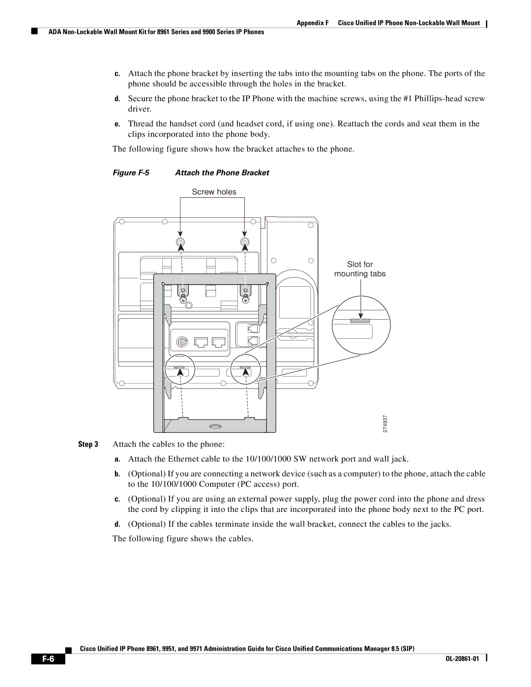
Figure F-5 Attach the Phone Bracket
Figure F-6
Remove Phone from Non-Lockable Wall Mount
Figure F-7 Attach phone to wall bracket
Figure F-8 Tab location
Figure F-9
345743
Screws Anchors Phone bracket
Before You Begin
Figure F-13 Bracket Installation
Figure F-14 Attach Phone Bracket
Figure F-15
Figure F-16 Attach Phone to Wall Bracket
Figure F-17
Figure F-18
OL-20861-01
Numerics
IN-1
Cast
Technical specifications Using Ldap directories
Call waiting Capf Certificate Authority Proxy Function
IN-2
DND
IN-3
USB
Using Wired Headset port Hold Hold reversion Http
Ethernet Statistics screen
HTTP, description Https
IN-5
MIC
Cast CDP Dhcp Http Rtcp RTP SIP TCP Tftp UDP
IN-6
IN-7
Intentionally
Trust List Security profiles
IN-8
IN-9
VPN Tftp
DNS
IN-10