Cisco Systems Cisco CRS-1 manual Chassis Power System, Safety Guidelines

Models: Cisco CRS-1

1 146
Download 146 pages 43.57 Kb
Page 24
Image 24

Chapter 1 Overview

Chassis Power System

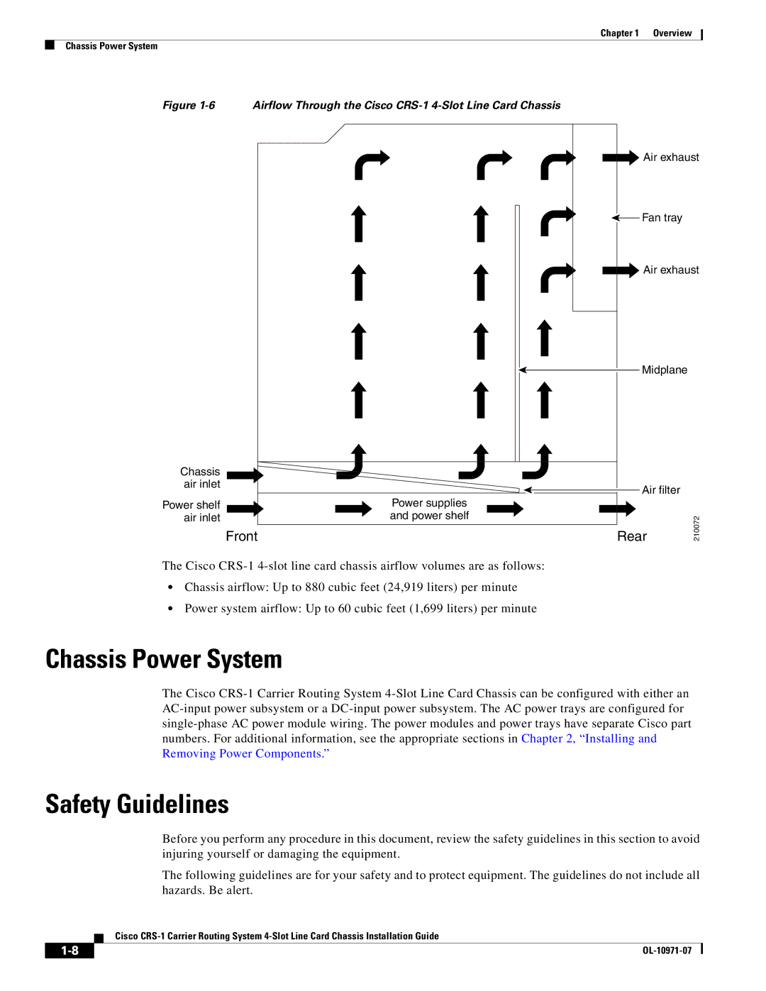
Figure 1-6 Airflow Through the Cisco CRS-1 4-Slot Line Card Chassis

Chassis air inlet

Power shelf


Power supplies

air inlet


and power shelf


Front

The Cisco CRS-1 4-slot line card chassis airflow volumes are as follows:

Chassis airflow: Up to 880 cubic feet (24,919 liters) per minute

Power system airflow: Up to 60 cubic feet (1,699 liters) per minute

Chassis Power System

Air exhaust

Fan tray

Air exhaust

Midplane

Air filter

Rear

210072

The Cisco CRS-1 Carrier Routing System 4-Slot Line Card Chassis can be configured with either an AC-input power subsystem or a DC-input power subsystem. The AC power trays are configured for single-phase AC power module wiring. The power modules and power trays have separate Cisco part numbers. For additional information, see the appropriate sections in Chapter 2, “Installing and Removing Power Components.”

Safety Guidelines

Before you perform any procedure in this document, review the safety guidelines in this section to avoid injuring yourself or damaging the equipment.

The following guidelines are for your safety and to protect equipment. The guidelines do not include all hazards. Be alert.

Cisco CRS-1 Carrier Routing System 4-Slot Line Card Chassis Installation Guide

1-8

OL-10971-07


Page 24
Image 24
Cisco Systems Cisco CRS-1 manual Chassis Power System, Safety Guidelines