Chapter 4 Installing and Removing SFCs, RPs, MSCs, PLIMs, and Associated Components
How to Install or Remove a Modular Services Card
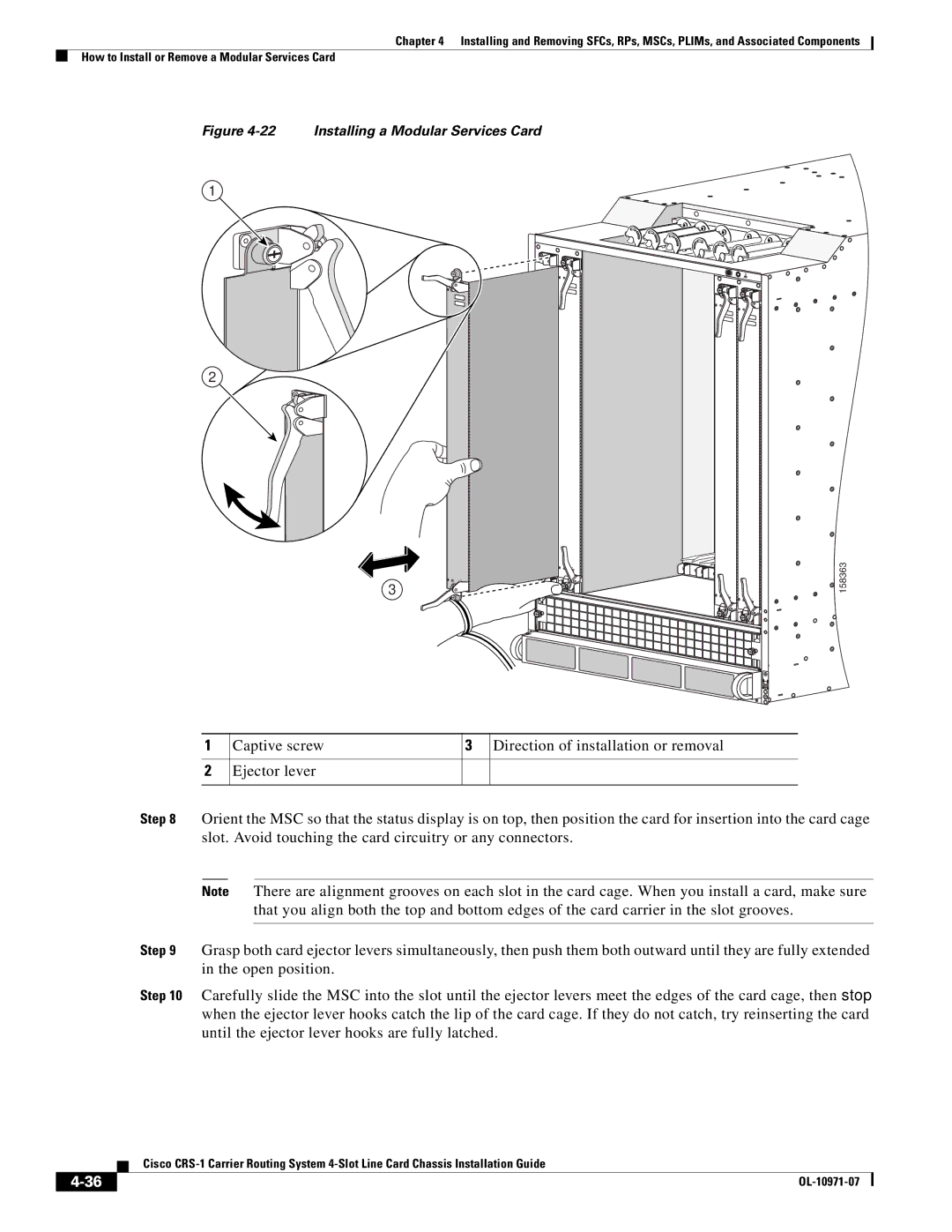
Figure 4-22 Installing a Modular Services Card
1
2
3
158363 |
1
2
Captive screw | 3 Direction of installation or removal |
Ejector lever
Step 8 Orient the MSC so that the status display is on top, then position the card for insertion into the card cage slot. Avoid touching the card circuitry or any connectors.
Note There are alignment grooves on each slot in the card cage. When you install a card, make sure that you align both the top and bottom edges of the card carrier in the slot grooves.
Step 9 Grasp both card ejector levers simultaneously, then push them both outward until they are fully extended in the open position.
Step 10 Carefully slide the MSC into the slot until the ejector levers meet the edges of the card cage, then stop when the ejector lever hooks catch the lip of the card cage. If they do not catch, try reinserting the card until the ejector lever hooks are fully latched.
| Cisco |
|