Cisco Systems manual Removing a Power Supply, Power Supply on the Cisco CRS-1 4-Slot Router

Models: Cisco CRS-1

1 146
Download 146 pages 43.57 Kb
Page 54
Image 54

Chapter 2 Installing and Removing Power Components

Removing a Power Supply

What to Do Next

After performing this task, you may connect the power shelf to the power source (see the “About Installing and Removing the Power Components” section on page 2-1, replace any front cosmetic covers, and power up the chassis (see the “Powering the Chassis Up or Down” section on page 2-4).

Removing a Power Supply

This section describes how to remove a power supply in the Cisco CRS-1 4-slot line card chassis. The power supplies can be an AC or DC power supplies (however, mixed types are not permitted). The AC power supply converts facility AC power into the DC power necessary to power the cards and modules in the chassis. Each AC power supply has its own pair of cooling fans, which draws air through the power supply.

For complete information on regulatory compliance and safety, see Cisco CRS-1 Carrier Routing System Regulatory Compliance and Safety Information.

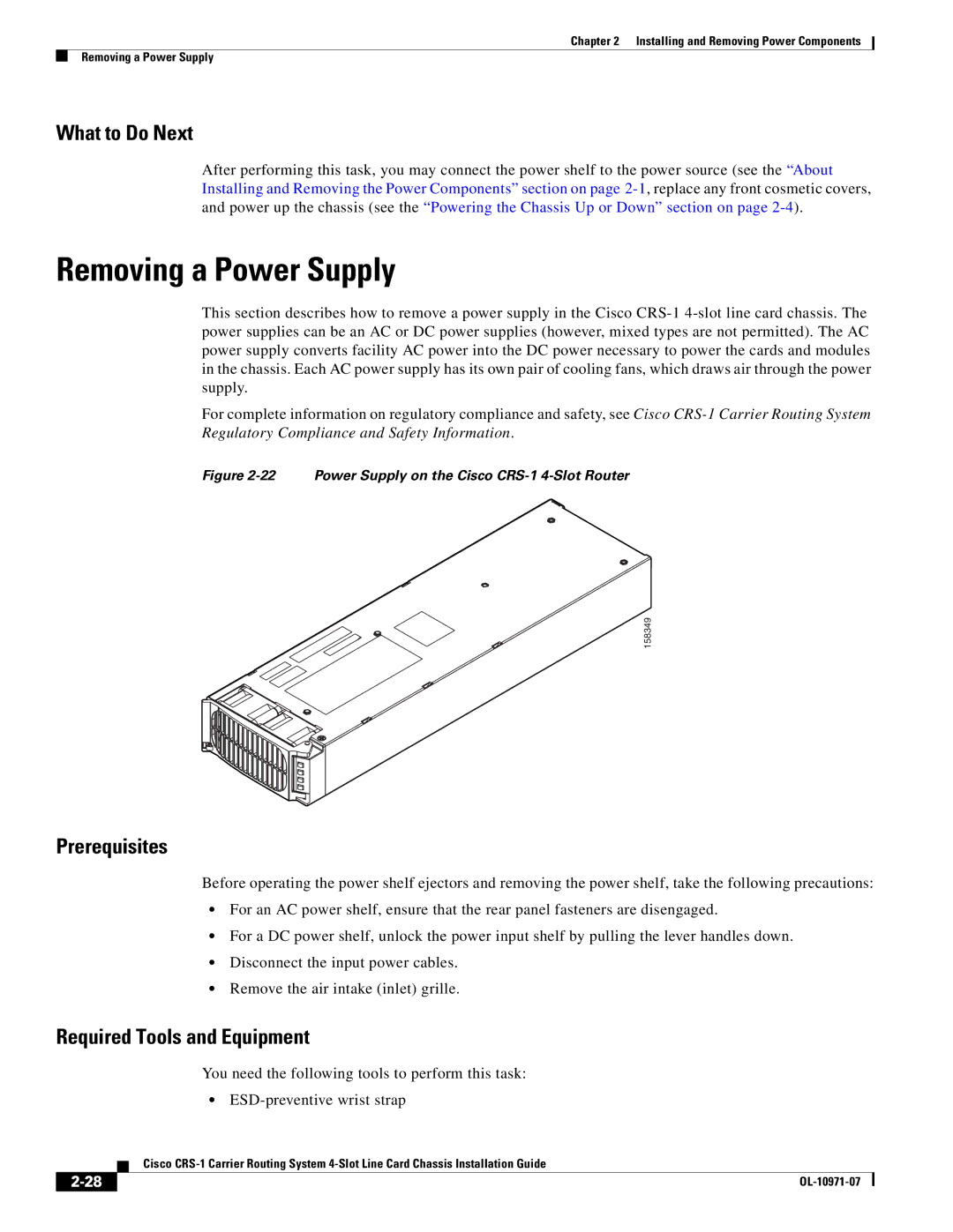
Figure 2-22 Power Supply on the Cisco CRS-1 4-Slot Router

158349

Prerequisites

Before operating the power shelf ejectors and removing the power shelf, take the following precautions:

For an AC power shelf, ensure that the rear panel fasteners are disengaged.

For a DC power shelf, unlock the power input shelf by pulling the lever handles down.

Disconnect the input power cables.

Remove the air intake (inlet) grille.

Required Tools and Equipment

You need the following tools to perform this task:

ESD-preventive wrist strap


Cisco CRS-1 Carrier Routing System 4-Slot Line Card Chassis Installation Guide

2-28

OL-10971-07

Page 54
Image 54
Cisco Systems manual Removing a Power Supply, Power Supply on the Cisco CRS-1 4-Slot Router