Chapter 2 Installing and Removing Power Components
Installing a DC Power Shelf
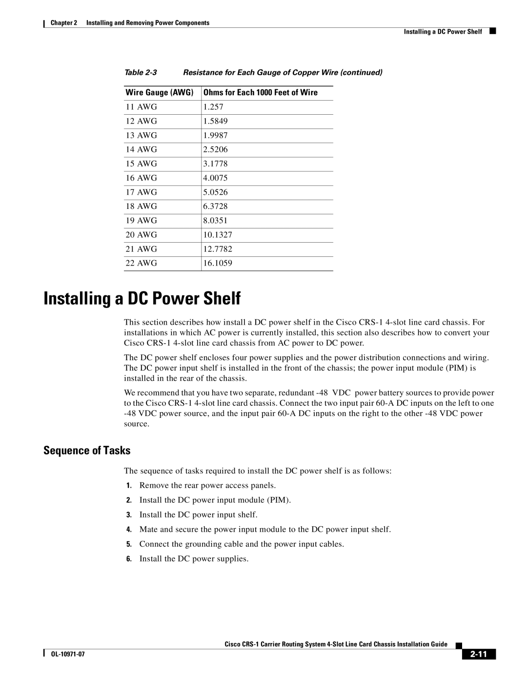
Table | Resistance for Each Gauge of Copper Wire (continued) | ||
|
|
| |
Wire Gauge (AWG) | Ohms for Each 1000 Feet of Wire | ||
|
|
|
|
11 AWG |
| 1.257 |
|
|
|
|
|
12 AWG |
| 1.5849 |
|
|
|
|
|
13 AWG |
| 1.9987 |
|
|
|
|
|
14 AWG |
| 2.5206 |
|
|
|
|
|
15 AWG |
| 3.1778 |
|
|
|
|
|
16 AWG |
| 4.0075 |
|
|
|
|
|
17 AWG |
| 5.0526 |
|
|
|
|
|
18 AWG |
| 6.3728 |
|
|
|
|
|
19 AWG |
| 8.0351 |
|
|
|
|
|
20 AWG |
| 10.1327 |
|
|
|
|
|
21 AWG |
| 12.7782 |
|
|
|
|
|
22 AWG |
| 16.1059 |
|
|
|
|
|
Installing a DC Power Shelf
This section describes how install a DC power shelf in the Cisco
The DC power shelf encloses four power supplies and the power distribution connections and wiring. The DC power input shelf is installed in the front of the chassis; the power input module (PIM) is installed in the rear of the chassis.
We recommend that you have two separate, redundant
Sequence of Tasks
The sequence of tasks required to install the DC power shelf is as follows:
1.Remove the rear power access panels.
2.Install the DC power input module (PIM).
3.Install the DC power input shelf.
4.Mate and secure the power input module to the DC power input shelf.
5.Connect the grounding cable and the power input cables.
6.Install the DC power supplies.
|
| Cisco |
|
| |
|
|
| |||
|
|
|
| ||
|
|
|
| ||