Chapter 2 Installing and Removing Power Components
DC Power Systems on the Cisco CRS-1 4-Slot Router
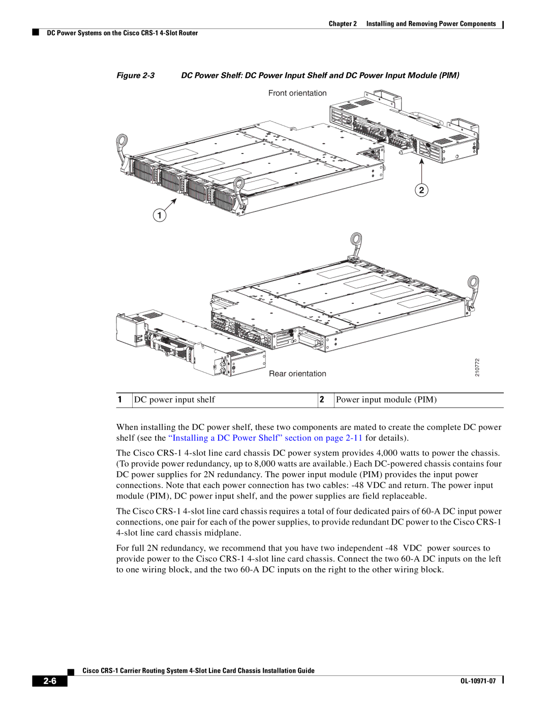
Figure 2-3 DC Power Shelf: DC Power Input Shelf and DC Power Input Module (PIM)
Front orientation
2
1
Rear orientation
DC power input shelf | 2 | Power input module (PIM) |
| | |
When installing the DC power shelf, these two components are mated to create the complete DC power shelf (see the “Installing a DC Power Shelf” section on page 2-11for details).
The Cisco CRS-1 4-slot line card chassis DC power system provides 4,000 watts to power the chassis. (To provide power redundancy, up to 8,000 watts are available.) Each DC-powered chassis contains four DC power supplies for 2N redundancy. The power input module (PIM) provides the input power connections. Note that each power connection has two cables: -48 VDC and return. The power input module (PIM), DC power input shelf, and the power supplies are field replaceable.
The Cisco CRS-1 4-slot line card chassis requires a total of four dedicated pairs of 60-A DC input power connections, one pair for each of the power supplies, to provide redundant DC power to the Cisco CRS-1 4-slot line card chassis midplane.
For full 2N redundancy, we recommend that you have two independent -48 VDC power sources to provide power to the Cisco CRS-1 4-slot line card chassis. Connect the two 60-A DC inputs on the left to one wiring block, and the two 60-A DC inputs on the right to the other wiring block.
Cisco CRS-1 Carrier Routing System 4-Slot Line Card Chassis Installation Guide