Chapter 2 Installing and Removing Power Components
Installing a DC Power Shelf
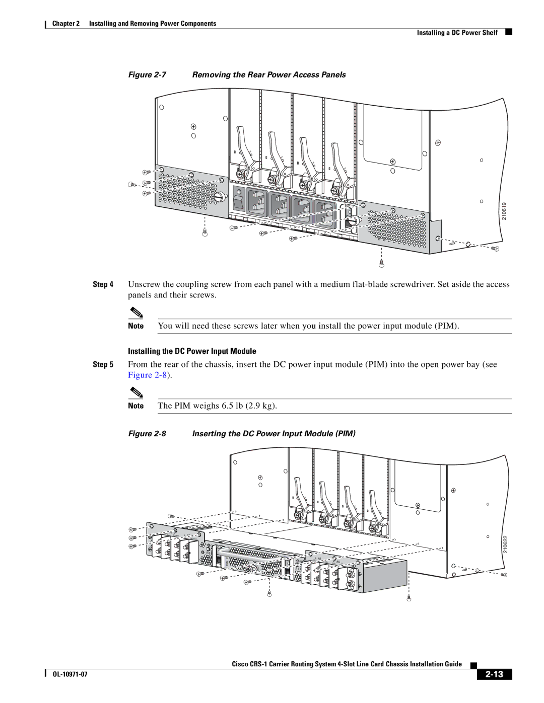
Figure 2-7 Removing the Rear Power Access Panels
STATUS
ATUS
ST
STATUS
STATUS
SIDE A
210619
Step 4 Unscrew the coupling screw from each panel with a medium
Note You will need these screws later when you install the power input module (PIM).
Installing the DC Power Input Module
Step 5 From the rear of the chassis, insert the DC power input module (PIM) into the open power bay (see Figure
Note The PIM weighs 6.5 lb (2.9 kg).
Figure 2-8 Inserting the DC Power Input Module (PIM)
+ (RTN)
B1 | – |
| (- |
|
+ | B0 | – |
(RTN) | (- | |
|
|
ON | SIDE B |
| |
B1 B0 |
|
Side B
S
STATU
S
STATU
S
STATU
S
STATU
| SIDE A |
| + | A1 | – |
|
|
|
| ON | (RTN) | + | A0 |
| |||
|
| (- |
| |||||
|
|
|
| – | ||||
|
|
|
|
|
| (RTN) | (- | |
|
| A1 A0 |
|
|
|
|
| |
A |
|
|
|
|
|
|
| |
Side |
|
|
|
|
|
|
|
|
210622
|
| Cisco |
|
| |
|
|
| |||
|
|
|
| ||
|
|
|
| ||