Chapter 2 Installing and Removing Power Components
Removing a DC Power Shelf
Steps
To remove the DC power shelf, follow these steps:
Step 1 Attach the
Bring Down All Power to the Chassis
Step 2 Power down the chassis:
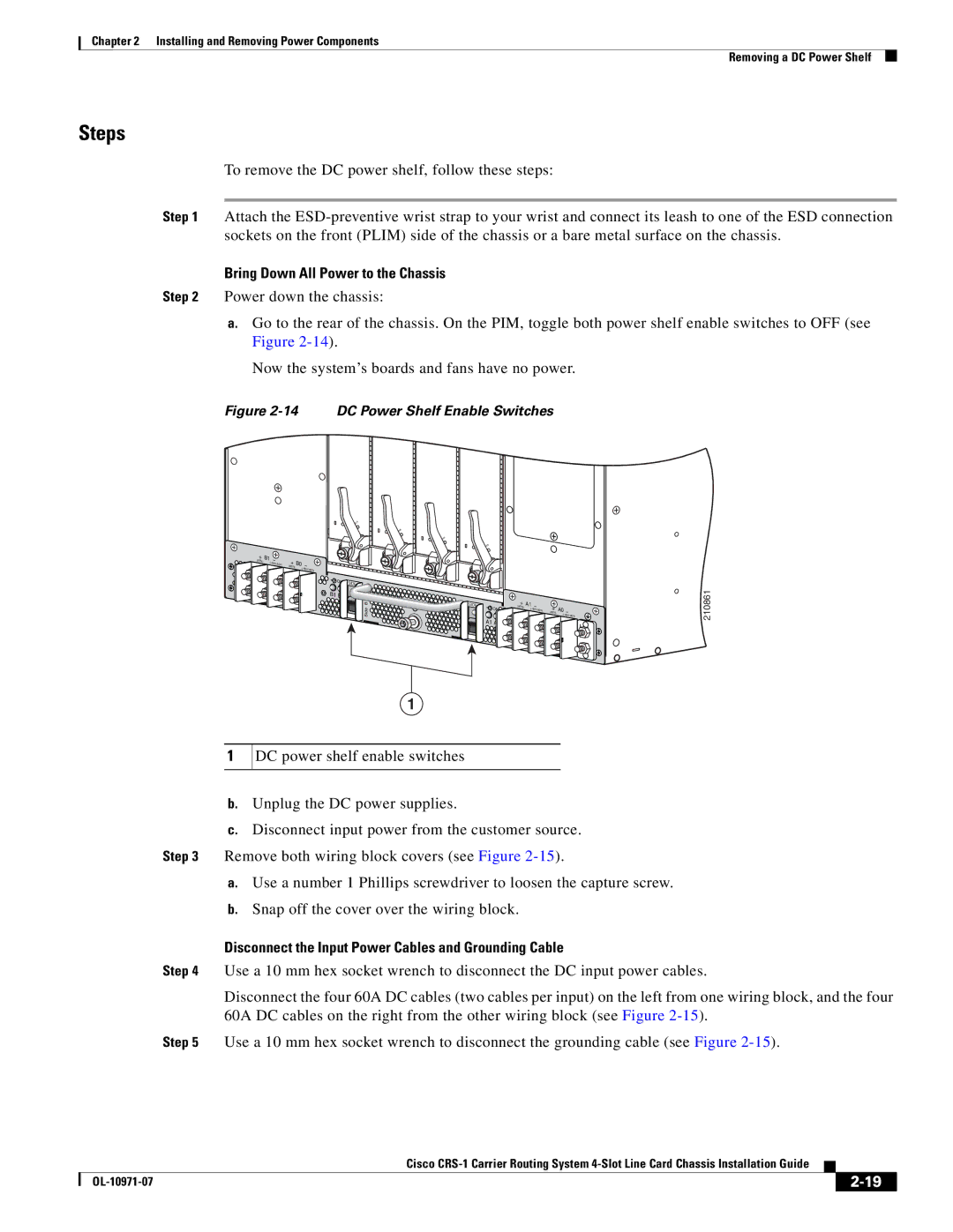
a.Go to the rear of the chassis. On the PIM, toggle both power shelf enable switches to OFF (see Figure
Now the system’s boards and fans have no power.
Figure 2-14 DC Power Shelf Enable Switches
+ (RTN)
B1 | – |
| (- |
|
+ (RTN)
S
STATU
S
STATU
S
STATU
B0 | – |
|
| (- |
|
|
| |
| ON | SIDE B |
|
| |
| B1 B0 |
|
|
| B |
|
| Side |
S
STATU
| SIDE A |
| + | A1 | – |
|
|
|
|
| ON | (RTN) | (- | + | A0 |
| |
|
|
|
| – | ||||
|
|
|
|
|
| (RTN) | (- | |
|
| A1 A0 |
|
|
|
|
| |
A |
|
|
|
|
|
|
| |
Side |
|
|
|
|
|
|
|
|
210861
1
1
DC power shelf enable switches
b.Unplug the DC power supplies.
c.Disconnect input power from the customer source.
Step 3 Remove both wiring block covers (see Figure
a.Use a number 1 Phillips screwdriver to loosen the capture screw.
b.Snap off the cover over the wiring block.
Disconnect the Input Power Cables and Grounding Cable
Step 4 Use a 10 mm hex socket wrench to disconnect the DC input power cables.
Disconnect the four 60A DC cables (two cables per input) on the left from one wiring block, and the four 60A DC cables on the right from the other wiring block (see Figure
Step 5 Use a 10 mm hex socket wrench to disconnect the grounding cable (see Figure
|
| Cisco |
|
| |
|
|
| |||
|
|
|
| ||
|
|
|
| ||