Chapter 2 Installing and Removing Power Components
Installing a DC Power Shelf
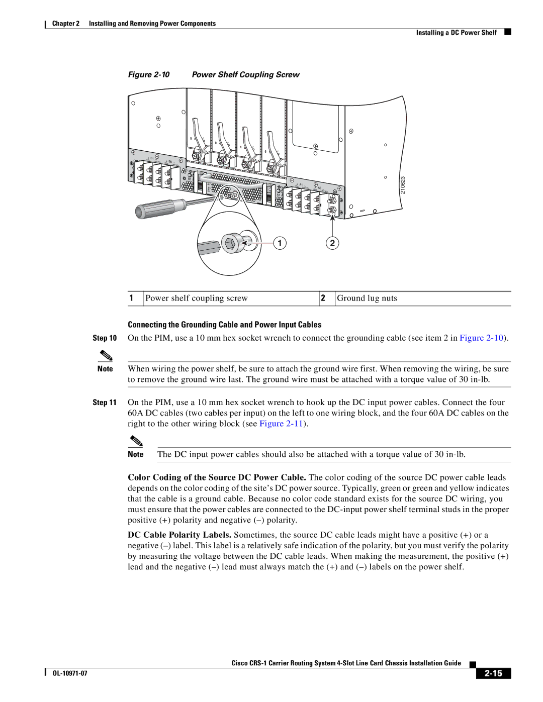
Figure 2-10 Power Shelf Coupling Screw
S
STATU
S
STATU
S
STATU
S
STATU
+ | B1 | – |
|
|
|
|
(RTN) | (- | + | B0 |
|
| |
|
| – |
| |||
|
|
| (RTN) | (- |
| |
|
|
|
|
|
| |
|
|
|
|
| ON | SIDE B |
|
|
|
|
|
| |
|
|
|
|
| B1 B0 |
|
B | SIDE A |
| + | A1 | – |
|
|
|
Side |
| ON | (RTN) | (- | + | A0 |
| |
|
|
| ||||||
|
|
|
|
| (RTN) | (- | ||
|
| A1 A0 |
|
|
| – | ||
| A |
|
|
|
|
|
| |
| Side |
|
|
|
|
|
|
|
12
210623
1
Power shelf coupling screw
2
Ground lug nuts
Connecting the Grounding Cable and Power Input Cables
Step 10 On the PIM, use a 10 mm hex socket wrench to connect the grounding cable (see item 2 in Figure
Note When wiring the power shelf, be sure to attach the ground wire first. When removing the wiring, be sure to remove the ground wire last. The ground wire must be attached with a torque value of 30
Step 11 On the PIM, use a 10 mm hex socket wrench to hook up the DC input power cables. Connect the four 60A DC cables (two cables per input) on the left to one wiring block, and the four 60A DC cables on the right to the other wiring block (see Figure
Note The DC input power cables should also be attached with a torque value of 30
Color Coding of the Source DC Power Cable. The color coding of the source DC power cable leads depends on the color coding of the site’s DC power source. Typically, green or green and yellow indicates that the cable is a ground cable. Because no color code standard exists for the source DC wiring, you must ensure that the power cables are connected to the
DC Cable Polarity Labels. Sometimes, the source DC cable leads might have a positive (+) or a negative
|
| Cisco |
|
| |
|
|
| |||
|
|
|
| ||
|
|
|
| ||