Chapter 2 Installing and Removing Power Components
DC Power Systems on the Cisco
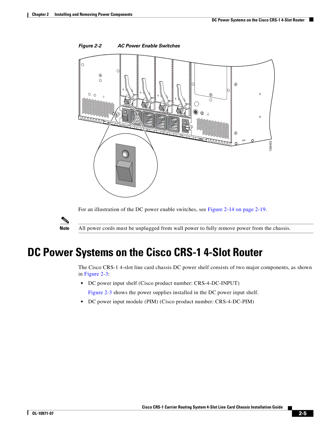
Figure 2-2 AC Power Enable Switches
S
STATU
S
STATU
S
STATU
S
STATU
158455
For an illustration of the DC power enable switches, see Figure
Note All power cords must be unplugged from wall power to fully remove power from the chassis.
DC Power Systems on the Cisco CRS-1 4-Slot Router
The Cisco
•DC power input shelf (Cisco product number:
Figure 2-3 shows the power supplies installed in the DC power input shelf.
•DC power input module (PIM) (Cisco product number: CRS-4-DC-PIM)
Cisco
|
| ||
|
|