Chapter 2 Installing and Removing Power Components
DC Power Systems on the Cisco CRS-1 4-Slot Router
DC Power Shelf Guidelines
At sites where the Cisco CRS-1 4-slot line card chassis is equipped with a DC power input shelf and power supplies, observe the following guidelines:
•All power connection wiring should follow the rules and regulations in the National Electrical Code (NEC) and any local codes.
•Each DC-input power entry module connection is rated at 60-A maximum. A dedicated, commensurately rated DC power source is required for each power supply connection.
•Each power supply requires one -48 VDC input, or four inputs for each power shelf (in which each input consists of a pair of positive and negative wires), and one power-shelf grounding wire.
•For DC power cables, we recommend that you use commensurately rated, high-strand-count copper wire cable. Each DC power supply requires one -48 VDC input, which means that there are two wires for each power supply, or eight total wires (four pairs) for each power shelf, plus the grounding wire. The length of the wires depends on the router’s location. These wires are not available from Cisco Systems; they are available from any commercial vendor.
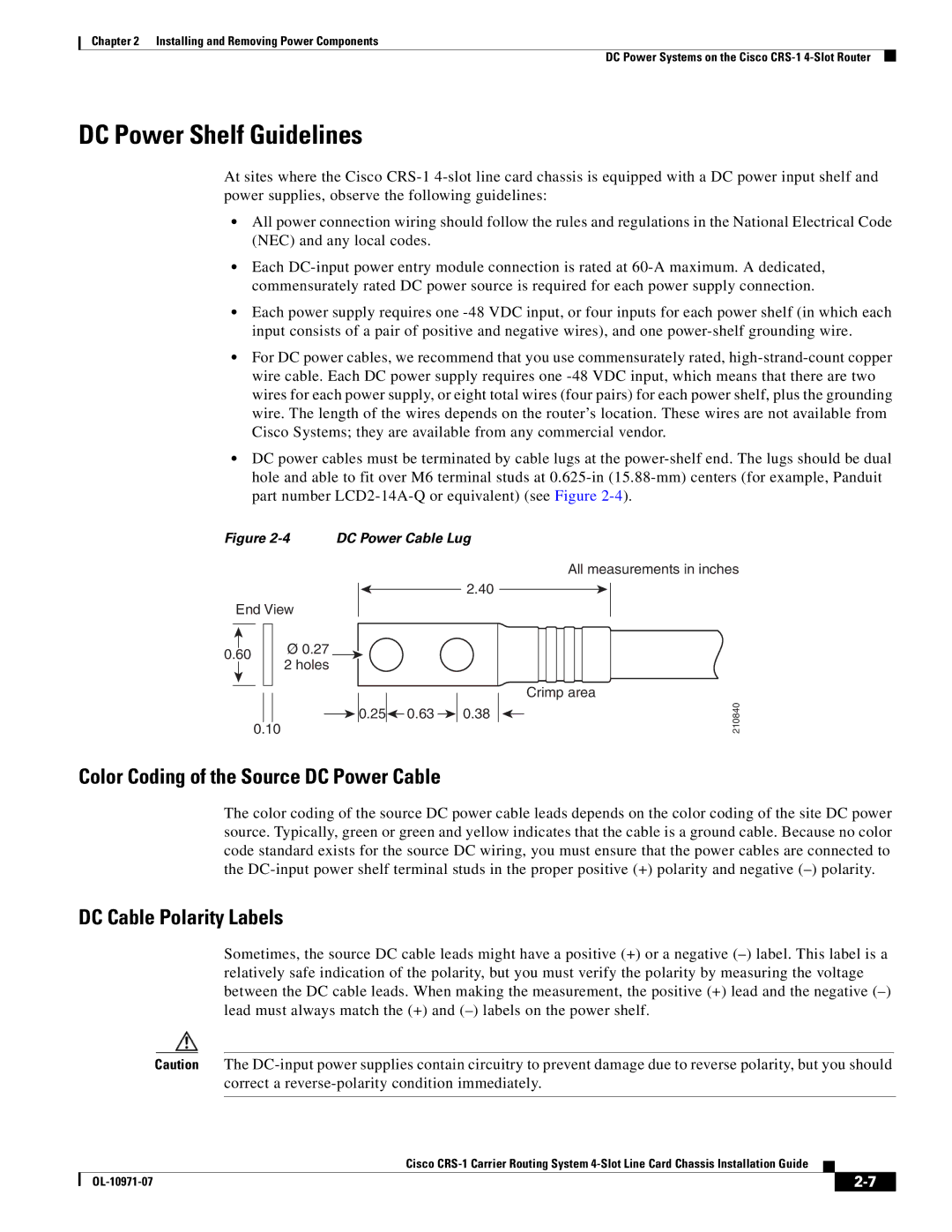
•DC power cables must be terminated by cable lugs at the power-shelf end. The lugs should be dual hole and able to fit over M6 terminal studs at 0.625-in (15.88-mm) centers (for example, Panduit part number LCD2-14A-Q or equivalent) (see Figure 2-4).
All measurements in inches
Crimp area
210840
Color Coding of the Source DC Power Cable
The color coding of the source DC power cable leads depends on the color coding of the site DC power source. Typically, green or green and yellow indicates that the cable is a ground cable. Because no color code standard exists for the source DC wiring, you must ensure that the power cables are connected to the DC-input power shelf terminal studs in the proper positive (+) polarity and negative (–) polarity.
DC Cable Polarity Labels
Sometimes, the source DC cable leads might have a positive (+) or a negative (–) label. This label is a relatively safe indication of the polarity, but you must verify the polarity by measuring the voltage between the DC cable leads. When making the measurement, the positive (+) lead and the negative (–) lead must always match the (+) and (–) labels on the power shelf.
Caution The DC-input power supplies contain circuitry to prevent damage due to reverse polarity, but you should correct a reverse-polarity condition immediately.
Cisco CRS-1 Carrier Routing System 4-Slot Line Card Chassis Installation Guide