Chapter 4 Installing and Removing SFCs, RPs, MSCs, PLIMs, and Associated Components
About Installing and Removing Cards and Associated Components
Guidelines for Card Installation and Removal
This section contains the general guidelines for card installation and removal.
Online insertion and removal (OIR) is supported, enabling you to remove and install cards while the Cisco
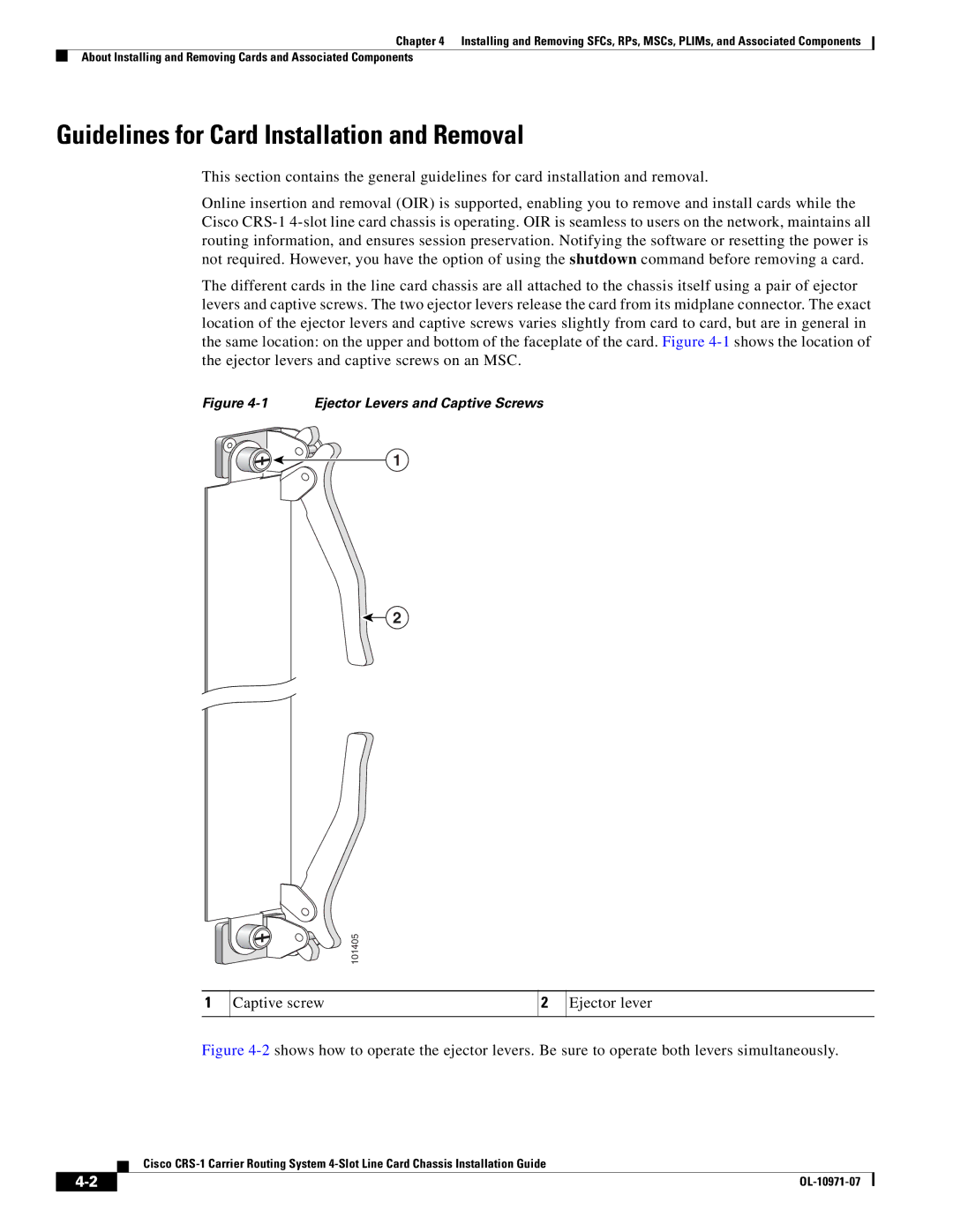
The different cards in the line card chassis are all attached to the chassis itself using a pair of ejector levers and captive screws. The two ejector levers release the card from its midplane connector. The exact location of the ejector levers and captive screws varies slightly from card to card, but are in general in the same location: on the upper and bottom of the faceplate of the card. Figure
Figure 4-1 Ejector Levers and Captive Screws
1
2
1
| 101405 |
Captive screw | 2 Ejector lever |