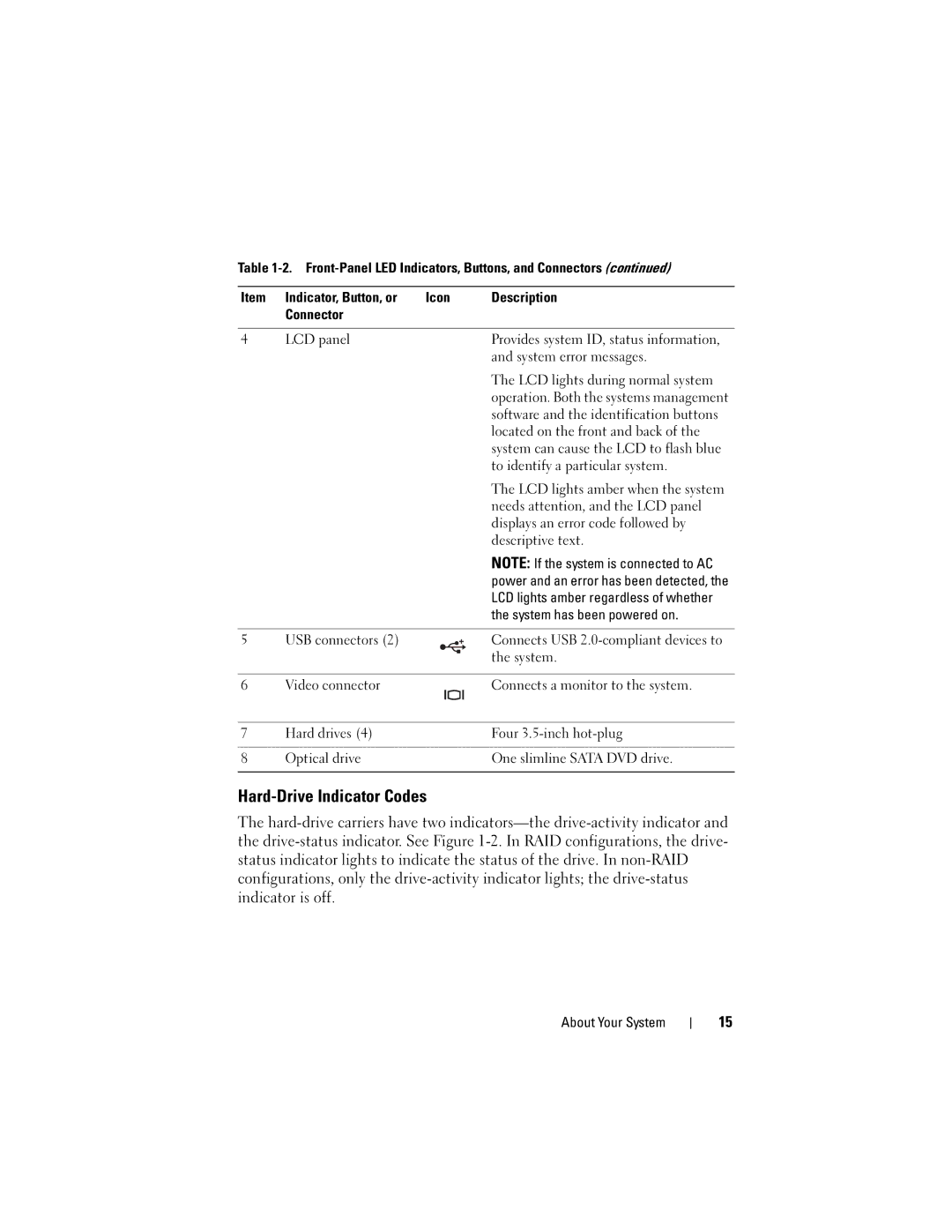
Table
Item | Indicator, Button, or | Icon | Description | |
| Connector |
|
|
|
|
|
|
|
|
4 | LCD panel |
|
| Provides system ID, status information, |
|
|
|
| and system error messages. |
|
|
|
| The LCD lights during normal system |
|
|
|
| operation. Both the systems management |
|
|
|
| software and the identification buttons |
|
|
|
| located on the front and back of the |
|
|
|
| system can cause the LCD to flash blue |
|
|
|
| to identify a particular system. |
|
|
|
| The LCD lights amber when the system |
|
|
|
| needs attention, and the LCD panel |
|
|
|
| displays an error code followed by |
|
|
|
| descriptive text. |
|
|
|
| NOTE: If the system is connected to AC |
|
|
|
| power and an error has been detected, the |
|
|
|
| LCD lights amber regardless of whether |
|
|
|
| the system has been powered on. |
|
|
|
|
|
5 | USB connectors (2) |
|
| Connects USB |
|
|
|
| the system. |
|
|
|
|
|
6 | Video connector |
|
| Connects a monitor to the system. |
|
|
|
|
|
7 | Hard drives (4) |
|
| Four |
|
|
|
|
|
8 | Optical drive |
|
| One slimline SATA DVD drive. |
|
|
|
|
|
Hard-Drive Indicator Codes
The
About Your System
15
