Timer/Counter/ Analyzers
Pendulum Instruments AB Sweden
Table of Contents
Arming Subsystem
Configure Function
Diagnostics Subsystem
Abort
Output Subsystem
Sense Command Subsystem
Common Commands
Memory Subsystem
Index
Getting Started
Index
Sections
Syntax Specification Form
Manual Conventions
Mnemonic Conventions
Setting Up Instrument
Setting the Gpib Address
Example Language
What can I do with the Bus?
Power-on
Testing the Bus
Interface Functions
Parallel Poll, PP0
Service Request, SR1
Listener Function, L4
Remote/Local, RL1
Bus Commands for the Benchtop User
INP2ATT110
Error Code
INPATT110
INPLEVlevel
These commands are from the Sense subsystem
Systpres or *RST
ACQHOFFTIMEtime
ACQAPERtime
FUNCfunctionchannel,channel
Calcavertypemaxminsdevmean Selects statistical function
SAVmemory location*RCLmemory location
Memory location can be any No. between 0
FUNCTOT1,2
All commands on this page are from the Sense subsystem
OUTPSCALscaling factor SYSTCOMMGPIBADDRAddress
This command is from the Sense subsystem
Default settings after *RST
Default settings after *RST
Introduction to Scpi
Compatibility
What is SCPI?
What is SCPI?
Reason for Scpi
Gpib
Management and Maintenance of Programs
How does Scpi Work in the Instrument?
Message Exchange Control protocol
How does Scpi Work in the Instrument?
Order of Execution
Deferred Commands
Sequential and Overlapped Commands
Protocol Requirements
Definitions
Remote Local Protocol
Program and Response Messages
Program and Response Messages
Syntax and Style
Syntax of Program Messages
Page
Notation Habit in Command Syntax
Syntax of Response Messages
Responses
SEND→ Inputfilteron
Moving down the Command Tree
Command Tree
Example
Keywords
Parameters
Numeric Data
Boolean Data
#218INPIMP50SENS10
Expression Data
Summary Other Data Types
SEND→ Systtouton or SYSTTOUT1
Data Types within Macros
Define Macro Command
Macros
Macro Names
How to Execute a Macro
Deleting Macros
Enabling and Disabling Macros
GMC? Get Macro Contents Query
Retrieve a Macro
LMC? Learn Macro Query
Status Reporting System
Introduction
Status Reporting System
Standardized Error Numbers
Error Reporting
Detecting Errors in the Queue
Read the Error/Event Queue
Execution Error
Device-specific Error
Query Error
Message Exchange Initialization
Initialization and Resetting
Reset Strategy
Bus Initialization
*CLS Command
*RST Command
Programming Examples
Introduction
Introduction
GW-Basic for National Instruments PC-IIA
Setting up the interface
Limit Testing
50 ‘
90 ‘ 100 ‘ 110 ‘ -- Enable arming, etc
180 ‘ Armdelay =
Frequency Profiling
270 WRT$ = Armdel + STR$ARMDELAY Call IBWRTCNT%, WRT$
PRINT#1, STR$ARMDELAY, LEFT$MSG$, INSTRMSG$, CHR$10
Call IBRDCNT%, MSG$
Call Ibwait CNT%, Mask
Fast Sampling
600 ‘ Close 620 END
510 MSG$ = SPACE$255
Status Reporting
130 ‘ -- SET Event Status Enable
180 ‘ -- SET Service Request Enable
260 ‘ -- Enter Command String and Send to Counter
520 ‘ -- Check Event Status BIT
650 ‘ -- Read Error Messages
410 ‘ -- Check Message Available BIT While SPR%
Lfpos
Call Ibrd CNT%, MSG$ Print Maximum = LEFT$MSG$, IBCNT%
Statistics
Print Waiting for Measurement to GET Ready
330 WRT$ = Calcavertype MAX CALCIMM? Call Ibwrt CNT%, WRT$
540 WRT$ = Calcavertype Sdev CALCIMM? Call Ibwrt CNT%, WRT$
Call Ibrd CNT%, MSG$ Print Minimum = LEFT$MSG$, IBCNT%
470 WRT$ = Calcavertype Mean CALCIMM? Call Ibwrt CNT%, WRT$
Call Ibrd CNT%, MSG$ Print Mean = LEFT$MSG$, IBCNT%
‘C’ for National Instruments PC-IIA
‘C’ for National Instruments
14 ‘C’ for National Instruments PC-IIA, Limit Testing
‘C’ for National Instruments PC-IIA, Real Data Format
Real Data Format
16 ‘C’ for National Instruments PC-IIA, Frequency Profiling
File
Ofp
Capture Profile
17 ‘C’ for National Instruments PC-IIA, Frequency Profiling
18 ‘C’ for National Instruments PC-IIA, Fast Sampling
‘C’ for National Instruments PC-IIA, Fast Sampliing
20 ‘C’ for National Instruments PC-IIA, Statistics
‘C’ for National Instruments PC-IIA, Statistics
This side is intentionally left blank
22 ‘C’ for National Instruments PC-IIA
Instrument Model
Function Instrument Examples Type
CALCulate
Measurement Function Block
INPut
SENSe
Order of Execution
Other Subsystems
MEASurement Function
CONFigure READ?
MEASurement Function
MEASure?
CONFigure INITiateFETCh?
Versatility of Measurement Com- mands
READ?
Using the Subsystems
Introduction
Calculate Subsystem
Mathematics
Statistics
Limit Monitoring
PM6680B, PM6685
PM6681
Calibration Subsystem
Configure Function
Configure Function
Format Subsystem
Time Stamp Readout Format
Input Subsystems
PM6685
PM6680B/PM6681
2Summary of PM6680B / PM6681 input amplifier settings
SEND→ MEASureFREQ?20MHz,1
CONFigure READ?
MEASure?
SEND→ MEASureFREQ?
CONFigureINITiateFETCh?
SEND→ READ?
Versatility of measurement com Mands
Output Subsystem
Scaling Factor
Same exponent, opposite sign
Resolution
Switchbox
Sense Command Subsystem
Prescaling
Status Subsystem
Using the Registers
Status Reporting Model
Status Structure
7654 3210
Using the Status Byte
Clearing/Setting all bits
Using the Queues
Status of the Error Message Queue EAV
Selecting Summary Message to Gen
Erate SRQ
Ic e
Status Event Registers
Setting up the Counter to Report Status
Reading and Clearing Status
Status Byte
Check & Action
Why Two Types of Registers?
Set up
Status Condition Registers
G i s t e r
Standard Status Registers
G ic a
A t u s B y t e
Summary, Standard Event Status Reporting
Standard Event Status Register
SCPI-defined Status Registers
Operation Status Group
Summary, Operation Status
Reporting
Summary Questionable
Questionable Data/Signal
Data/Signal Status Reporting
Status Group
Device-defined Status Structure
Error Queue
Power-on Status Clear
Preset the Status Reporting Structure
Summary, Device-defined Status Reporting
ARM-TRIG Trigger Configuration
Instrument Action
Trigger/Arming Subsystem
Structure of the Idle and Initiated States
Structure of an Event-detection Layer
Forward Traversing an Event-detection Layer
Backward Traversing an Event-detection Layer
TRG Trigger Command
When to use *TRG and GET
Triggering
E n t d e t e c t i o n l oa ny e er a c h a r m
E n t d e t e c t i o n l a y e r
How to Measure Fast
Stop
Controller Synchronization
Measurement Cycle Synchronization
Start
Rough Trigger
Subsystem
Description
Some Basic Commands
MEASMEM1? MEASMEM?1 RCL 1READ?
Command
MEASFREQ?
Data Format
ARMSTARTLAY2SOURceBUS
Individually Synchronized Measurements
Initcont and GET
Basic Measurement Method
Init + GET + FETCHARRay?
General Speed Improvements
Block Synchronized Measurements
READARRay?
Automatic Interpolator Calibration PM6680B/85
Time Measurement Resolution
Display Control
Gpib Data Format
Real Time Calculation
Measure
Ments/second
Block Measurements
Supervising a Process
Supervising a Process
Obvious Method
Optimal Method
Transfer to Controller Ascii Data Format Real Data Format
Speed Summary
Speed Summary
Dead Time Between Measurements Including
E e d D i v i d u a l l y s y n c . m e a s
PM6680B PM6681 PM6685
Block Synchronized Measurements
Speed Improvement Actions
Dead Time Between Measurements
Speed
Calculating the Measurement
Freq
Timesaving Com Time Gain in ms Sacrifice Mands
Single Speed Switch Command for PM6681
Single Speed Switch Command for PM6680B/85
Error Messages
Command Errors
Read the Error/Event Queue
Error Code 0 to
SEND→ SYSTemERRor? READ← -100, Command Error
Error Code -105 to -120
Ular error message is used when the counter cannot
Error Code -121 to
More specific error
Detect a more specific error
Error Code -151 to -170
Error Code -171 to
Error Code -200 to -221
Tect the more specific errors described for errors
Error Code -222 to
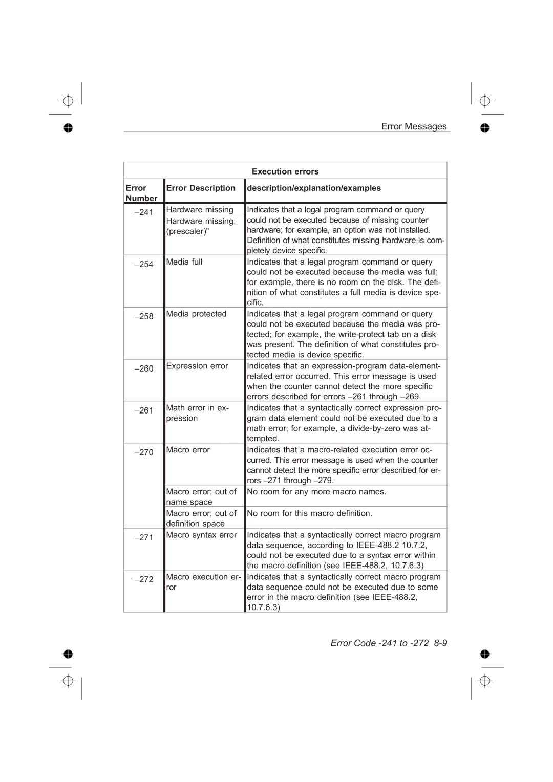
Execution errors
Error message is used when the counter cannot de
Error Code -241 to -272
Error Code -273 to
Header syntax
Macro label was already defined see
Error Code -300 to -350
Query errors
Error Code -400 to
Unsupported single Shot command
Error Code 1100 to -1139
Unsupported enu Merated command
Unsupported auto Command
Some PC controller cards has been known to do
Error Code 1150 to
Reset during bus
Output Read, but the waiting was broken by the operator
Parser error Generic error in the parser
Error Code 1214 to -1240
This page is intentionally left blank
Command Reference
Command Reference
Abort
Aborts all previous measurements if *WAI is not used
ABORt
Abort Measurement
PM6680B/81/85
Arming Subsystem
Send ARMCOUN100
ARM COUNt
No. of Measurements on each Bus arm
«Numeric valueMINMAX» PM6680B/81/85
External Events before Start Arming
ARM DELay
Delay after External Start Arming
ARM ECOunt
Bus Arming On/Off
ARM LAYer2
ARM LAYer2 SOURce
Bus Arming Override
External Arming Start Source
ARM SLOPe
ARM SOURce
External Arming Start Slope
External Events before Stop Arming
ARM Stop DELay
Delay after External Stop Arming
ARM Stop ECOunt
External Stop Arming Source
ARM Stop SLOPe
ARM Stop SOURce
External Stop Arming Slope
This page is intentionally left blank
Calculate Subsystem
Sample Size for Statistics
Enable Statistics
CALCulate AVERage COUNt
CALCulate AVERage STATe
Send Calcmathstat Oncalcmath X 10.7E6INIT *OPC
CALCulate AVERage Type
Statistical Type
Fetch calculated data
Recalculate Data
Enable Monitoring of Parameter Limits
CALCulate IMMediate
CALCulate LIMit
Set Low Limit
CALCulate LIMit FAIL?
CALCulate LIMit LOWer
Limit Fail
Check Against Lower Limit
Set Upper Limit
CALCulate LIMit LOWer STATe
CALCulate LIMit UPPer
Check Against Upper Limit
CALCulate LIMit UPPer STATe
Sendcalcmath X 10.7E6MATHSTATE ONREAD?
CALCulate Math
Select Mathematical Expression
Expression
No calculation
Enable Mathematics
This example switches on mathematics
CALCulate Math STATe
Send Calcstat
Enable Calculation
Switches on Post Processing
CALCulate STATe
Calibration Subsystem
Boolean Once
‘How to Measure Fast’
CALibration INTerpolator Auto
Calibration of Interpolator
Set up Instrument for Measurement
Configure Function
Send CONFFREQRAT@3,@1
CONFigure Measuring Function
Configure the counter for a single measurement
Parameters,channels
Send READARR?
CONFigure ARRay Measuring Function
Configure the counter for an array of measurements
Send Confarrper 7,5E-3,1E-6,@4
This page is intentionally left blank
Diagnostics Subsystem
This string calibrates both input a and input B
DIAGnosticCALibrationINPut12HYSTeresis
Input comparator hysteresis calibration
Send Diagcalinphyst Once
Display Subsystem
Display State
DISPlay ENABle
Where Boolean = 1 / on 0 / OFF
See also , ‘How to Measure Fast’
Fetch Function
Fetch One Result
FETCh?
FETCh ARRay?
Fetch an Array of Results
«fetch array sizeMAX»
Returned format data,data
Format Subsystem
Response Data Type
FORMat
Data Type for Status Messages
FORMat FIXed
FORMat SREGister
Response Data Format
Timestamping On/Off TimestampingOn/Off
FORMat TINFormation
Initiate Subsystem
Continuously Initiated
INITiate
INITiate CONTinuous
Initiate Measurement
Input B Not PM6685
Input Subsystems
INPut«12» ATTenuation
INPut«12» COUPling
AC/DC Coupling
Sensitivity
INPut FILTer
INPut HYSTeresis
Low Pass Filter
Send Inphystauto OFF
INPut HYSTeresis Auto
Auto Sensitivity
«BooleanONCE»
Fixed Trigger Level
INPut«12» IMPedance
INPut«12» LEVel
Input Impedance
Send Inplev 3.75LEVAUTO
INPut LEVel
Waveform compensation
«Decimal dataMAXMIN» PM6685
Send INP2LEVAUTO on
INPut LEVel Auto
Autotrigger
Send Inplevauto OFF
Autotrigger INPutAUTO?
INPut«124» SLOPe
INPut2COMMon
Trigger Slope
This page is intentionally left blank
Measurement Function
Set up the Instrument, Perform Measurement, and Read Data
RISETIME?
Tion, @1@3@4@5@6
Send MEASFREQ? @3 Read 1.78112526833E+009
MEASure Measuring Function?
Make one measurement
Parameters ,channels PM6680B/81/85
Ten measuring results will be returned
MEASure ARRay Measuring Function?
Make an array of measurements
Send MEASARRFREQ?
Memory Recall, Measure and Fetch Result
Data Format Command
MEASureMEMoryN?
MEASureMEMory?
Read +5.097555E-001
MEASure«DCYCle/PDUTycycle»
Positive Duty Cycle
Send MEASPDUT?
This example measures the frequency at input C
Expected value,resolution ,@«1234567» PM6680B/81/85
MEASure FREQuency?
Frequency
Expected value,resolution ,@«1234567»
MEASure FREQuency BURSt?
Burst Carrier Frequency
MEASure FREQuency PRF?
Pulse Repetition Frequency
Exp. val.,res.,@«1234567» PM6680B/81/85
Send MEASFREQRAT? @1,@3 Read 2.345625764333E+000
MEASure FREQuency RATio?
Fall-time
Frequency Ratio
Negative Peak Voltage
MEASure Volt MAXimum?
MEASure Volt MINimum?
Positive Peak Voltage
Positive Pulse Width
MEASure NWIDth?
MEASure PWIDth?
Negative Pulse Width
Negative duty cycle Duty Factor
MEASure«PDUTycycle/ DCYCle»?
MEASure«NDUTycycle»?
Positive duty cycle Duty Factor
Period
MEASure PHASe?
Phase
MEASure PERiod?
Rise-time
MEASure Volt PTPeak?
MEASure Rise TIME?
Peak-to-Peak Voltage
MEASure TINTerval?
Time-Interval
@«124»,@«124»
MEASure TOTalize ACCumulated?
Totalize X gated by Y, accumulated
Time for gate open,@«12456» ,@«12456» PM6680B PM6681
Send CONFTOTINPSLOPe neg
PM6680B/81/85CONFigure TOTalize CONTinuous
Totalize Manually
@«1246»,@«1246»
Totalize X start/stop by Y
MEASure TOTalize GATed?
MEASure TOTalize SSTop?
Totalize X gated by Y
Send MEASTOTTIM? 1,@1,@1
Totalize X-Y During a Preset Time
MEASure TOTalize TIMed?
Time for gate open ,@«124»,@«124»
This page is intentionally left blank
Memory Subsystem
Related Common Commands
Memory Free for results
MEMory DELete MACRo
MEMory Free SENSe?
Delete one Macro
Number of states available
Memory Free for Macros
Memory States
Bytes available, Bytes used
This page is intentionally left blank
Output Subsystem
Scaling Factor, Analog Output
Enable Analog Out
OUTPut
OUTPut SCALe
Perform Measurement and Read Data
Read Function
Send Conffreqinpfilt ONREAD?
Read one Result
Send Armcoun 10READARR?
READARRay?
Read an array of results
«array size for FETChMAX»
This page is intentionally left blank
Sense Subsystem command tree for PM6680B and PM6681
Sense Command Subsystem
Sense Subsystem command tree for PM6685
Decimal value 10 ms
ACQuisition APERture
Set the Measurement Time
«Decimal value MINMAX»
Hold Off, set event counter
ACQuisition Hoff
ACQuisition Hoff ECOunt
Hold Off On/Off
Hold Off Time
ACQuisition Hoff Mode
Hold Off Mode
ACQuisition Hoff Time
ACQuisition RESolution
AVERage COUNt
Average Samples
«Decimal dataMIN MAX»
High Speed Voltage Measurements
AVERage STATe
FREQuency RANGe LOWer
Average or Single?
Input channels PM6685
FUNCtion
Select Measuring Function
Functions and channels in PM6685
Input channels PM6680B and PM6681
Functions and channels in PM6680B and PM6681
Buffer
INTernal FORMat
Internal Format
Number of Results
Select Reference Oscillator
SDELay
BURST/PRF Synchronization Delay
ROSCillator SOURce
Gated Voltage Measurement
TOTalize Gate
VOLTageGATedSTATe
Gate On/Off
This page is intentionally left blank
Status Subsystem
Related Common Commands
STATus DREGister0?
STATus DREGister0 ENABle
Enable Device Status Reporting
Bit No Weight Condition
Read Operation Status Condition Register
STATus OPERation CONDition?
288
STATus OPERation ENABle
Enable Operation Status Reporting
Send Statoperenab
STATusPRESet values
STATusOPERation?
Read Operation Status, Event
STATus QUEStionable CONDition?
Read Questionable Data/Signal Condition Register
STATus QUEStionable?
STATus QUEStionable ENABle
Enable Questionable Data/Signal Status Reporting
Read Questionable Data/Signal Event Register
This page is intentionally left blank
System Subsystem
Related common command
Send Systcommgpibaddr
SYSTem ERRor?
SYSTem COMMunicate Gpib ADDRess
Set Gpib Address
See also Default settings on
SYSTem PRESet
Preset
Signal Detection
Read On-time
Read or Send Settings
SYSTem SET
SYSTem Time ELAPsed?
SYSTem Tout Time
Timeout On/Off
Timeout, Set
SYSTem Tout
System Version
SYSTem UNPRotect
SYSTem VERSion?
Unprotect
Test Subsystem
Select Self-tests
Select Check signal
TESTCHECk
Test SELect
Trigger Subsystem
TRIGgerCOUNt
No. of Triggerings on each Ext Arm start
Send Trigcoun
Common Commands
Send *CLS
Clear Status Command
Send Autofilt OFF
Define Macro
Send AMPLITUDE?
Read +3.46125461E-001+3.64852399E-001
SEND*EMC
Enable Macros
Enables macro expansion and execution
Decimal data PM6680B/81/85
Standard Event Status Enable
Event Status Enable Register 1 = enable
Operation Complete
Send *GMC? ‘AMPLITUDE?’
Event Status Register
Get Macro Definition
Macro label PM6680B/81/85
READAUTOFILT,AMPLITUDE?
Identification query
Learn Macro
Main
Learn Device Setup
Operation Complete
Send INIT*OPC
Bus option,Prescaler option
Operation Complete Query
Option Identification
Example 6 is Chapter
Removes all macro definitions
Power-on Status Clear
This example enables automatic power-on clearing
Purge Macros
Recall
Protected User Data
‘Macro name’ is the name of the macro you want to delete
Reset
This command removes an individual MACRo PM6680B/81/85
Default settings on
Save
Decimal data = a number between 1
Send *SAV
Service Request Enable Register 1 = enable
Service Request Enable
Read +3.2770536E+004
Status Byte Query
ARMSTARtLAYer2IMM *WAIFETCh?
Send ARMSTARTLAY2SOURCE BUS Send Initcont on
SENDMEASFREQ? *WAIMEASPDUT?
Integer = PM6680B Error PM6681, PM6685 Er Ror
Self Test
Wait-to-continue
Index
Average or Single? · · · · · · · · · · · · ·
Address
Auto
Auto calibration on/off· · · · · · · · · · · 9-24Average
Calculate
Command Error CME
Burst
Bus
ARMSEQuence1LAYer1ECOunt
CONFigureTOTalizeACCumulated
SENSeFREQuencyRANGeLOWer
STATusOPERationCONDition?
STATusQUEStionableCONDition?
Display
Delay
Device dependent Error DDE
Device Status Register
Fail Limit · · · · · · · · · · · · · · · · · · · · · · ·
Events
Execution
External Events before Start Arming
Initiated state · · · · · · · · · · · · · · · · · 6-28Input
Hysteresis · · · · · · · · · · · · · · · · · · · ·
Measuring
Lower Limit
Operation Status
Monitor
Result
Pulse
QUE · · · · · · · · · · · · · · · · · 9-130 9-131Query
Response
Speed
Settings
Set
Stop arming · · · · · · · · · · · · · · · · · 9-11Source
Test
Time
Time out For measurement TIO · · · · · · · 6-24Timebase
Upper Limit
See Also Command *TRG