L i f e B o o k 9 0 0 S e r i e s f r o m F u j i t s u
U s i n g Y o u r L i f e B o o k 9 0 0 S e r i e s
Type III cards are always Card 1 only. The PC Card Access indicator will flash if your software tries to access a PC Card even if none are installed.
NumLk Indicator
The NumLk indicator tells you the internal key- board is set in
CapsLock Indicator
The CapsLock indicator tells you when the key- board is set for all capital letters. Activate the capitals lock mode by pressing the CapsLock key on the keyboard. Deactivate the mode the same way you activated it.
Scr Lk Indicator
The Scr Lk indicator tells you when you are in scroll lock mode. You can activate or deactivate the scroll lock mode by pressing the Scr Lk/NumLk key. Deactivate the mode the same way you activated it.
On
Off
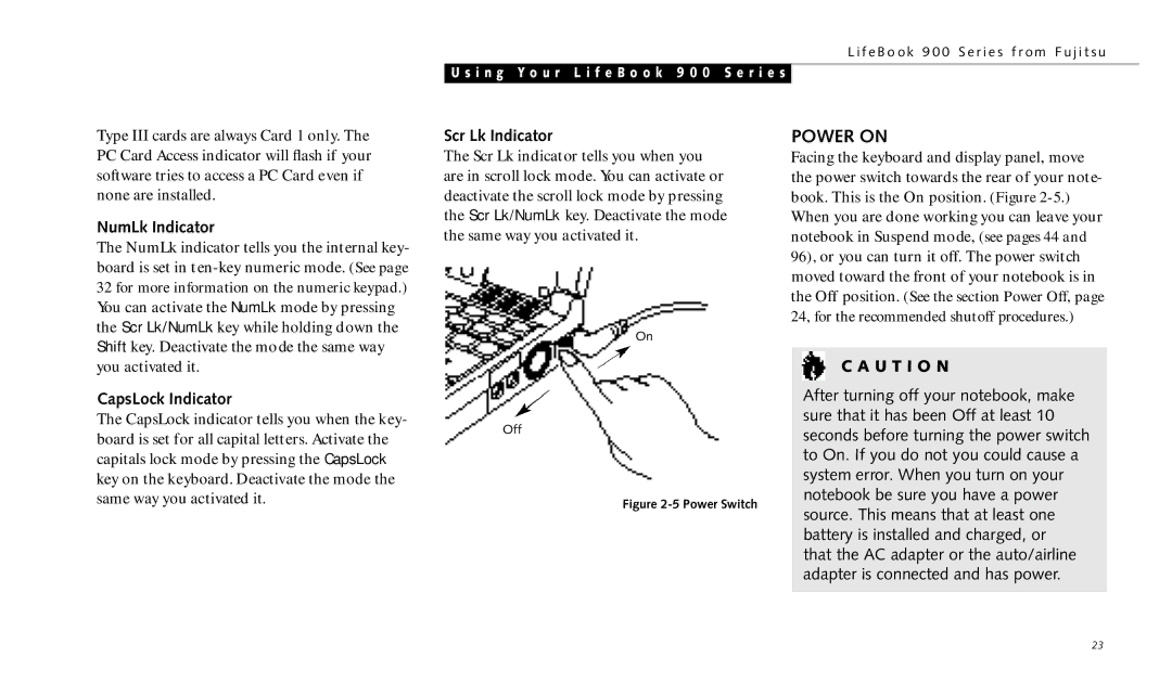
Figure 2-5 Power Switch
POWER ON
Facing the keyboard and display panel, move the power switch towards the rear of your note- book. This is the On position. (Figure
C A U T I O N
After turning off your notebook, make sure that it has been Off at least 10 seconds before turning the power switch to On. If you do not you could cause a system error. When you turn on your notebook be sure you have a power source. This means that at least one battery is installed and charged, or that the AC adapter or the auto/airline adapter is connected and has power.
23