L i f e B o o k 9 0 0 S e r i e s f r o m F u j i t s u
C o n f i g u r i n g Y o u r L i f e B o o k 9 0 0 S e r i e s
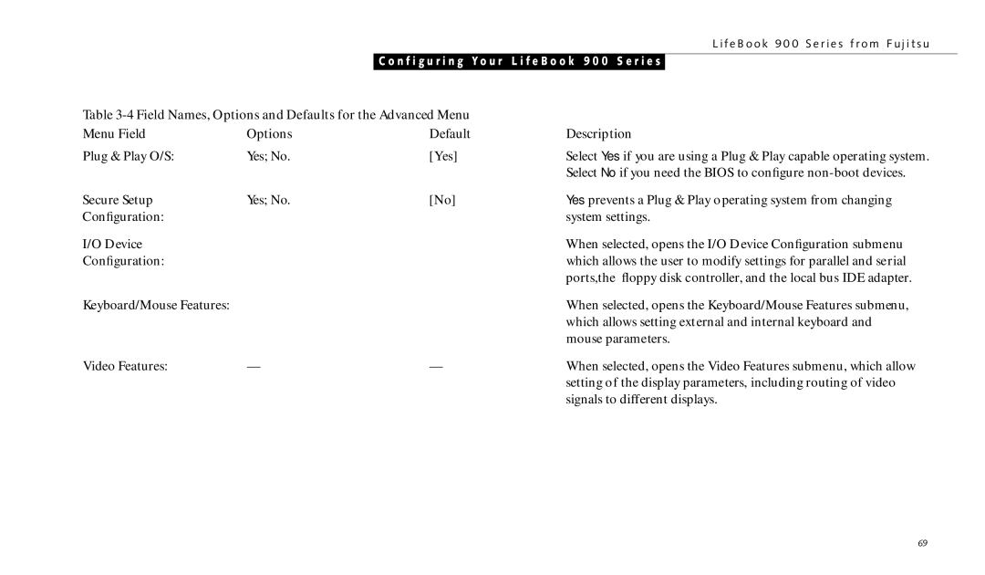
Table |
| ||
Menu Field | Options | Default | Description |
Plug & Play O/S: | Yes; No. | [Yes] | Select Yes if you are using a Plug & Play capable operating system. |
|
|
| Select No if you need the BIOS to configure |
Secure Setup | Yes; No. | [No] | Yes prevents a Plug & Play operating system from changing |
Configuration: |
|
| system settings. |
I/O Device |
|
| When selected, opens the I/O Device Configuration submenu |
Configuration: |
|
| which allows the user to modify settings for parallel and serial |
|
|
| ports,the floppy disk controller, and the local bus IDE adapter. |
Keyboard/Mouse Features: |
|
| When selected, opens the Keyboard/Mouse Features submenu, |
|
|
| which allows setting external and internal keyboard and |
|
|
| mouse parameters. |
Video Features: | — | — | When selected, opens the Video Features submenu, which allow |
|
|
| setting of the display parameters, including routing of video |
|
|
| signals to different displays. |
69