L i f e B o o k 9 0 0 S e r i e s f r o m F u j i t s u
C o n f i g u r i n g Y o u r L i f e B o o k 9 0 0 S e r i e s
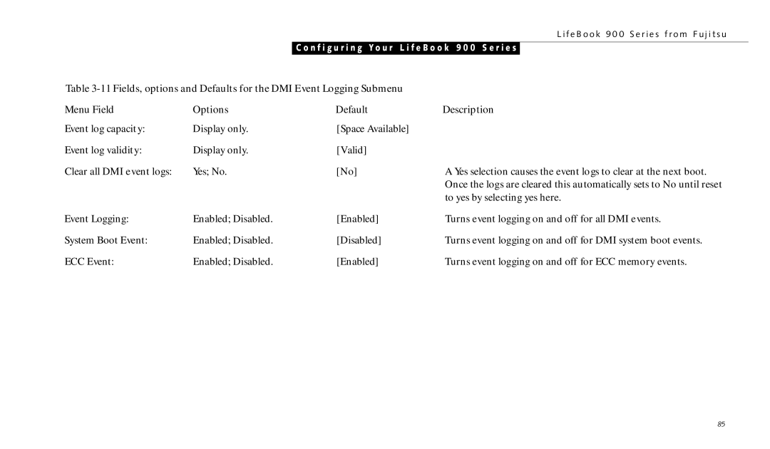
Table |
| ||
Menu Field | Options | Default | Description |
Event log capacity: | Display only. | [Space Available] |
|
Event log validity: | Display only. | [Valid] |
|
Clear all DMI event logs: | Yes; No. | [No] | A Yes selection causes the event logs to clear at the next boot. |
|
|
| Once the logs are cleared this automatically sets to No until reset |
|
|
| to yes by selecting yes here. |
Event Logging: | Enabled; Disabled. | [Enabled] | Turns event logging on and off for all DMI events. |
System Boot Event: | Enabled; Disabled. | [Disabled] | Turns event logging on and off for DMI system boot events. |
ECC Event: | Enabled; Disabled. | [Enabled] | Turns event logging on and off for ECC memory events. |
85