Cal Mode Sel: Writing a one (1) in this field sets the calibration system to calibrate voltage. Writing a zero (0) in this field sets the calibration system to calibrate current. This bit controls a relay that requires approximately 5 mS to change states.
Cal Mux En: Writing a one (1) in this field enables the Cal Mux. Writing a zero (0) in this field disables the Cal Mux.
Cal Mux Chan Address: The address of the channel selected is written to this field. The channel address, expressed in hexadecimal, has values from 016 through F16 corresponding to channels 1 through 16, respectively. This field only has effect when the Cal Mux En field is set to one (1).
A/D Scale: This bit changes the A/D scaling. When set to 0, normal A/D scaling is used. When set to 1, A/D scaling is divided by 13.7. This bit is used by
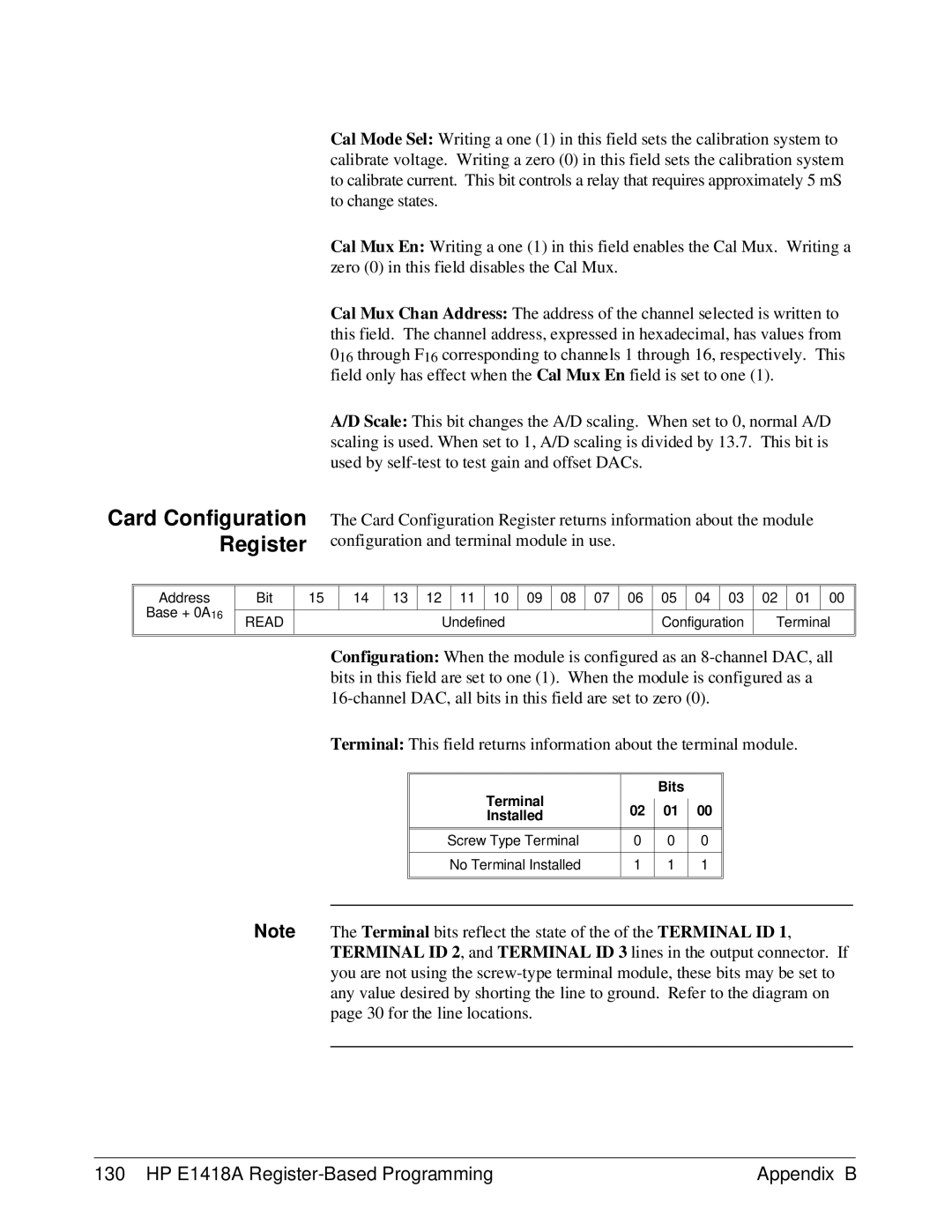
Card Configuration Register
The Card Configuration Register returns information about the module configuration and terminal module in use.
Address
Base + 0A16
Bit | 15 | 14 | 13 | 12 |
| 11 | 10 | 09 | 08 | 07 | 06 | 05 | 04 | 03 | 02 | 01 | 00 |
|
|
|
|
|
|
|
|
|
|
|
|
|
|
|
|
|
|
READ |
|
|
|
| Undefined |
|
|
|
| Configuration | Terminal | ||||||
|
|
|
|
|
|
|
|
|
|
|
|
|
|
|
|
|
|
Configuration: When the module is configured as an
Terminal: This field returns information about the terminal module.
| Terminal |
|
| Bits |
|
|
|
| 02 |
| 01 |
| 00 |
| |
|
|
|
| ||||
| Installed |
|
|
| |||
|
|
|
|
|
|
| |
|
|
|
|
|
|
|
|
|
|
|
|
|
|
|
|
| Screw Type Terminal | 0 |
| 0 |
| 0 |
|
|
|
|
|
|
|
|
|
| No Terminal Installed | 1 |
| 1 |
| 1 |
|
|
|
|
|
|
|
|
|
|
|
|
|
|
|
|
|
|
|
|
|
|
|
|
|
Note The Terminal bits reflect the state of the of the TERMINAL ID 1, TERMINAL ID 2, and TERMINAL ID 3 lines in the output connector. If you are not using the
130 HP E1418A | Appendix B |