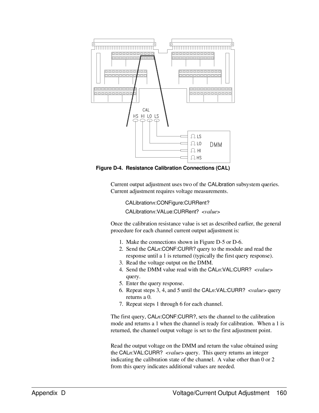
Figure D-4. Resistance Calibration Connections (CAL)
Current output adjustment uses two of the CALibration subsystem queries. Current adjustment requires voltage measurements.
CALibrationn:CONFigure:CURRent?
CALibrationn:VALue:CURRent? <value>
Once the calibration resistance value is set as described earlier, the general procedure for each channel current output adjustment is:
1.Make the connections shown in Figure
2.Send the CALn:CONF:CURR? query to the module and read the response until a 1 is returned (typically the first query response).
3.Read the voltage output on the DMM.
4.Send the DMM value read with the CALn:VAL:CURR? <value> query.
5.Enter the query response.
6.Repeat steps 3, 4, and 5 until the CALn:VAL:CURR? <value> query returns a 0.
7.Repeat steps 1 through 6 for each channel.
The first query, CALn:CONF:CURR?, sets the channel to the calibration mode and returns a 1 when the channel is ready for calibration. When a 1 is returned, the channel output voltage is set to the first adjustment point.
Read the output voltage on the DMM and return the value obtained using the CALn:VAL:CURR? <value> query. This query returns an integer indicating the calibration state of the channel. A value other than 0 or 2 from this query indicates additional values are needed.
Appendix D | Voltage/Current Output Adjustment 160 |