Notes
Main_DAC
Immediate
Registers
Each incremental value of the A24 Window offsets the window by 32 bytes. Up to 512 bytes of A24 space can be pointed to.
A24 Window values 816 through F16 point to Calibration Registers. Calibration Registers 0010016 through 001BE16 are located in
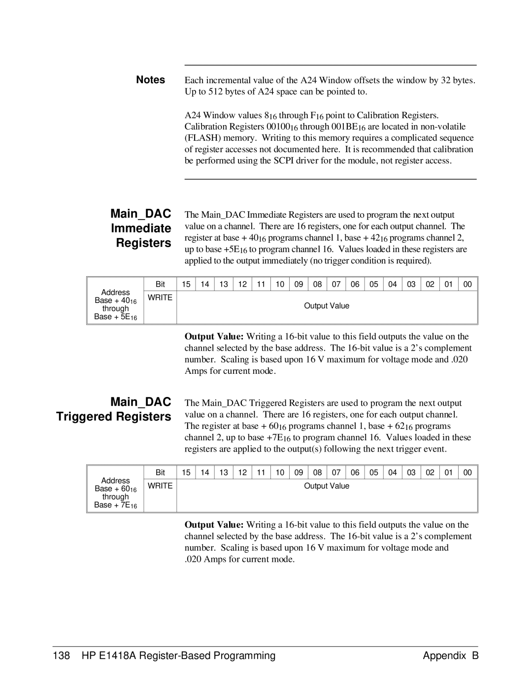
The Main_DAC Immediate Registers are used to program the next output value on a channel. There are 16 registers, one for each output channel. The register at base + 4016 programs channel 1, base + 4216 programs channel 2, up to base +5E16 to program channel 16. Values loaded in these registers are applied to the output immediately (no trigger condition is required).
Address
Base + 4016
through
Base + 5E16
Bit | 15 | 14 | 13 | 12 | 11 | 10 | 09 | 08 | 07 | 06 | 05 | 04 | 03 | 02 | 01 | 00 |
|
|
|
|
|
|
|
|
|
|
|
|
|
|
|
|
|
WRITE
Output Value
Output Value: Writing a
Main_DAC Triggered Registers
The Main_DAC Triggered Registers are used to program the next output value on a channel. There are 16 registers, one for each output channel. The register at base + 6016 programs channel 1, base + 6216 programs channel 2, up to base +7E16 to program channel 16. Values loaded in these registers are applied to the output(s) following the next trigger event.
Address
Base + 6016
through
Base + 7E16
Bit | 15 | 14 | 13 | 12 | 11 | 10 | 09 |
| 08 | 07 |
| 06 | 05 | 04 | 03 | 02 | 01 | 00 |
|
|
|
|
|
|
|
|
|
|
|
|
|
|
|
|
|
|
|
WRITE |
|
|
|
|
|
|
| Output Value |
|
|
|
|
|
|
| |||
|
|
|
|
|
|
|
|
|
|
|
|
|
|
|
|
|
|
|
Output Value: Writing a
.020 Amps for current mode.
138 HP E1418A | Appendix B |