Device Type Register
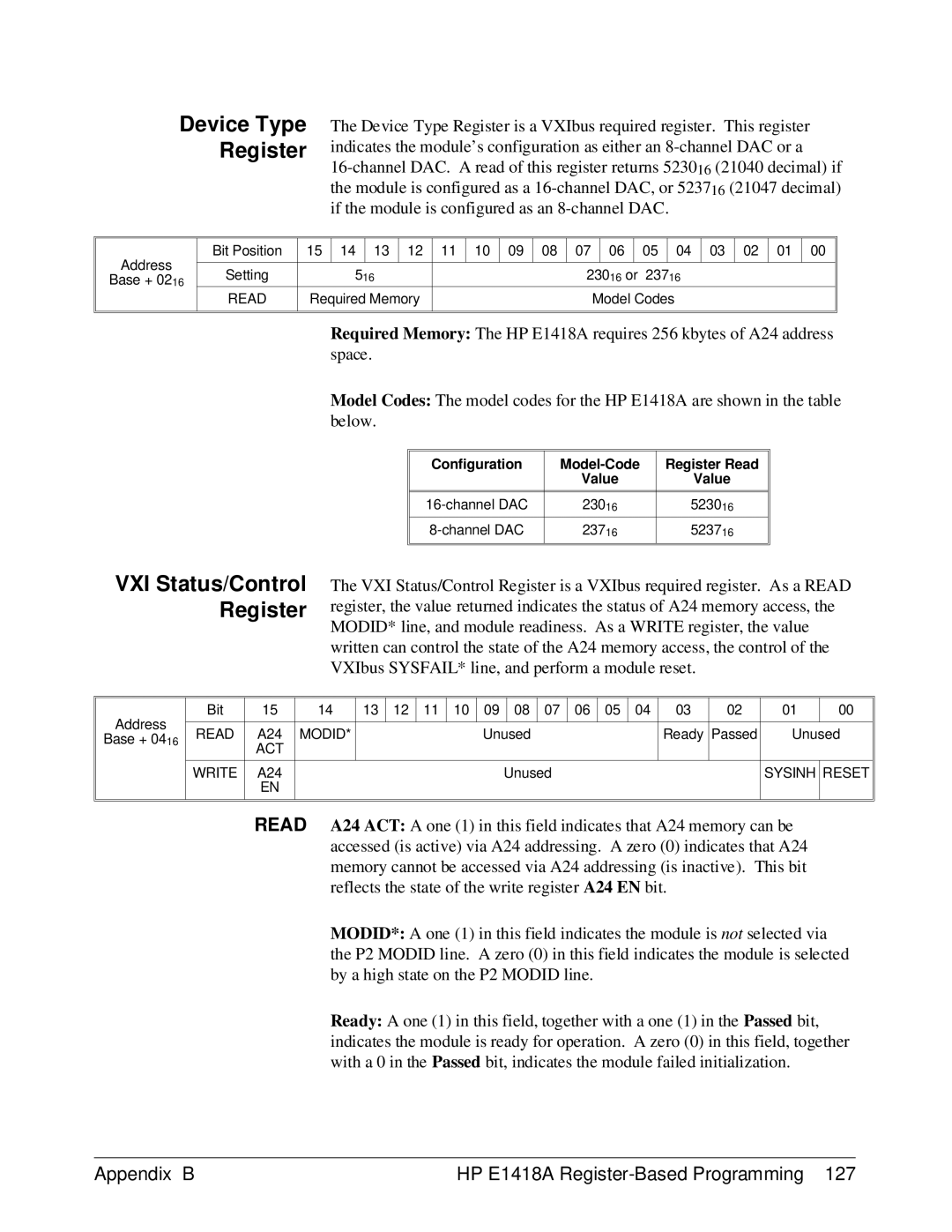
The Device Type Register is a VXIbus required register. This register indicates the module’s configuration as either an
Address | Bit Position | 15 | 14 | 13 | 12 | 11 | 10 | 09 | 08 | 07 | 06 | 05 | 04 | 03 | 02 | 01 | 00 |
|
|
|
|
|
|
|
|
|
|
|
|
|
|
|
|
| |
Setting | 516 |
|
|
|
|
| 23016 or 23716 | ||||||||||
Base + 0216 |
|
|
|
|
| ||||||||||||
|
|
|
|
|
|
|
|
|
|
|
|
|
|
|
|
| |
| READ | Required Memory |
|
|
|
| Model Codes | ||||||||||
|
|
|
|
|
|
|
|
|
|
|
|
|
|
|
|
|
|
|
|
|
|
|
|
|
|
|
|
|
|
|
|
|
|
|
|
Required Memory: The HP E1418A requires 256 kbytes of A24 address space.
Model Codes: The model codes for the HP E1418A are shown in the table below.
Configuration | Register Read | |
| Value | Value |
|
|
|
|
|
|
23016 | 523016 | |
|
|
|
23716 | 523716 | |
|
|
|
|
|
|
VXI Status/Control Register
The VXI Status/Control Register is a VXIbus required register. As a READ register, the value returned indicates the status of A24 memory access, the MODID* line, and module readiness. As a WRITE register, the value written can control the state of the A24 memory access, the control of the VXIbus SYSFAIL* line, and perform a module reset.
Address
Base + 0416
Bit | 15 | 14 | 13 | 12 | 11 | 10 | 09 |
| 08 | 07 | 06 | 05 | 04 | 03 | 02 | 01 | 00 |
|
|
|
|
|
|
|
|
|
|
|
|
|
|
|
|
| |
READ | A24 | MODID* |
|
|
|
| Unused |
|
|
|
| Ready | Passed | Unused | |||
| ACT |
|
|
|
|
|
|
|
|
|
|
|
|
|
|
|
|
|
|
|
|
|
|
|
|
|
|
|
|
|
|
| |||
WRITE | A24 |
|
|
|
|
|
| Unused |
|
|
|
|
| SYSINH | RESET | ||
| EN |
|
|
|
|
|
|
|
|
|
|
|
|
|
|
|
|
|
|
|
|
|
|
|
|
|
|
|
|
|
|
|
|
|
|
READ A24 ACT: A one (1) in this field indicates that A24 memory can be accessed (is active) via A24 addressing. A zero (0) indicates that A24 memory cannot be accessed via A24 addressing (is inactive). This bit reflects the state of the write register A24 EN bit.
MODID*: A one (1) in this field indicates the module is not selected via the P2 MODID line. A zero (0) in this field indicates the module is selected by a high state on the P2 MODID line.
Ready: A one (1) in this field, together with a one (1) in the Passed bit, indicates the module is ready for operation. A zero (0) in this field, together with a 0 in the Passed bit, indicates the module failed initialization.
Appendix B | HP E1418A |