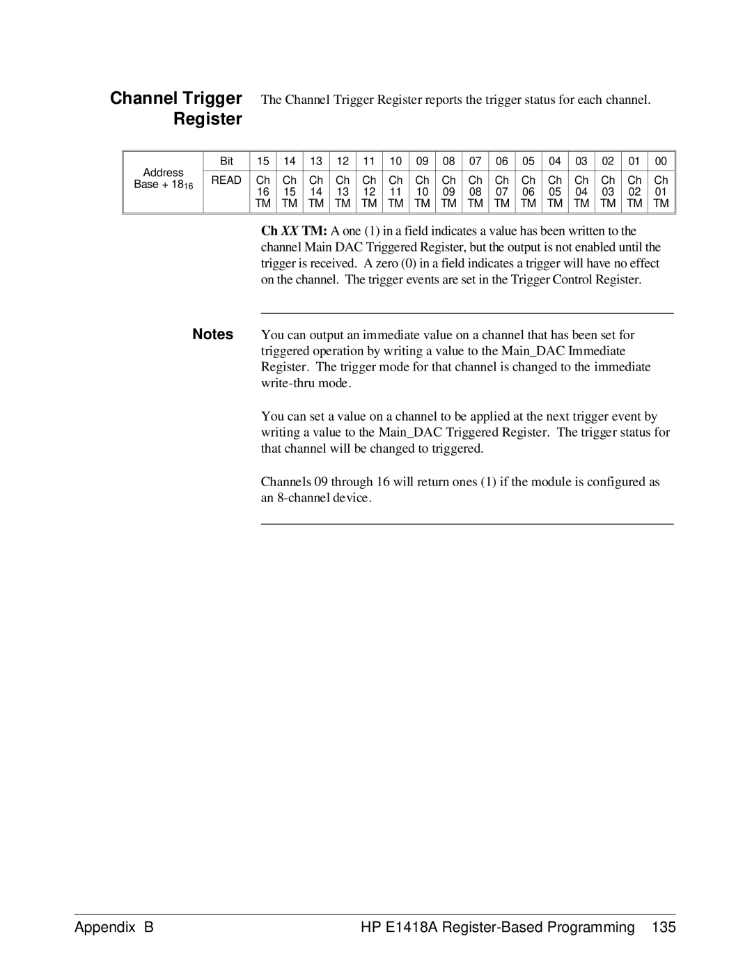
Channel Trigger | The Channel Trigger Register reports the trigger status for each channel. |
| |||||||||||||||||
| Register |
|
|
|
|
|
|
|
|
|
|
|
|
|
|
|
|
| |
|
|
|
|
|
|
|
|
|
|
|
|
|
|
|
|
|
|
|
|
| Address | Bit | 15 | 14 | 13 | 12 | 11 | 10 | 09 | 08 | 07 | 06 | 05 | 04 | 03 | 02 | 01 |
| 00 |
|
|
|
|
|
|
|
|
|
|
|
|
|
|
|
|
|
|
| |
READ | Ch | Ch | Ch | Ch | Ch | Ch | Ch | Ch | Ch | Ch | Ch | Ch | Ch | Ch | Ch |
| Ch | ||
| Base + 1816 |
| |||||||||||||||||
|
| 16 | 15 | 14 | 13 | 12 | 11 | 10 | 09 | 08 | 07 | 06 | 05 | 04 | 03 | 02 |
| 01 | |
|
|
|
| ||||||||||||||||
|
|
| TM | TM | TM | TM | TM | TM | TM | TM | TM | TM | TM | TM | TM | TM | TM |
| TM |
|
|
|
|
|
|
|
|
|
|
|
|
|
|
|
|
|
|
|
|
|
|
|
|
|
|
|
|
|
|
|
|
|
|
|
|
|
|
|
|
Ch XX TM: A one (1) in a field indicates a value has been written to the channel Main DAC Triggered Register, but the output is not enabled until the trigger is received. A zero (0) in a field indicates a trigger will have no effect on the channel. The trigger events are set in the Trigger Control Register.
Notes You can output an immediate value on a channel that has been set for triggered operation by writing a value to the Main_DAC Immediate Register. The trigger mode for that channel is changed to the immediate
You can set a value on a channel to be applied at the next trigger event by writing a value to the Main_DAC Triggered Register. The trigger status for that channel will be changed to triggered.
Channels 09 through 16 will return ones (1) if the module is configured as an
Appendix B | HP E1418A |