Manuals
/
HP
/
TV and Video
/
TV Converter Box
HP
E1418A
manual
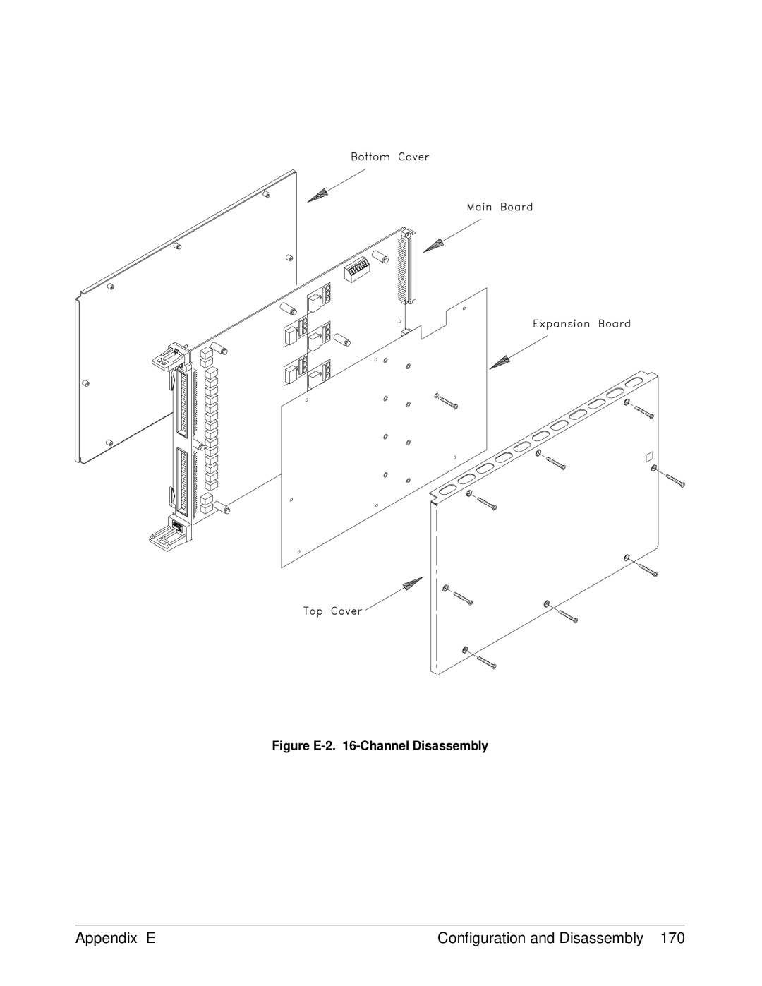
Figure E-2 -Channel Disassembly
Models:
E1418A
1
170
187
187
Download
187 pages
37.67 Kb
167
168
169
170
171
172
173
174
Page 170
Image 170
Figure
E-2.
16-Channel
Disassembly
Appendix E
Configuration and Disassembly 170
Page 169
Page 171
Page 170
Image 170
Page 169
Page 171
Contents
Contents
HP E1418A Scpi Command Reference
Appendix B. HP E1418A Register-Based Programming
Appendix D. Voltage/Current Output Adjustment
Page
Page
Certification
Warranty
Limitation Of Warranty
Exclusive Remedies
Safety Symbols
Documentation History
Declaration of Conformity
According to ISO/IEC Guide 22 and EN
HP E1418A User’s Manual
Business Reply Mail
HP E1418A User’s Manual
Using This Chapter
Module Description
Module Setup and Installation Chapter
Description
Description Use
A Functional Block Diagram
Functional Description
Channels 1-8 main board and V XIbus backplane circuitry
Front Panel Connectors
HP E1418A Front Panel Connector Pinout
Setting the Logical Address Switch
Setting the Logical Address
Module Installation
Installation in a Mainframe
Chapter Module Setup and Installation
Terminal Modules
Screw-Type Terminal Module Standard
Wiring the Terminal Module
Wiring the HP E1418A Terminal Module
From previous
Attaching the Terminal Module
Attaching the HP E1418A Terminal Module
Removing the Terminal Module
Removing the HP E1418A Terminal Module
10. Option A3E Crimp-and-Insert Connector
Terminal Module Options
Single-Conductor
Contact
11. Option A3H Ribbon Cable Connector
Terminal Module Connectors
12. HP E1418A Terminal Module Connector Pinout
Configuring the Terminal Module
13. P/J and V/I Jumpers
Options A3E and A3H Terminals
Terminal Module Connections
Voltage Current Output Connections
Combining
Channels
Connecting an External Trigger Source
16. External Trigger Connections
Using the CAL Output Terminals
17. Calbus Connections
Initial Operation
Module Identification
Programming Examples
Querying Module Identification and Configuration
String returned should be similar to one of the following
Decimal Integer
Configuration
Returned Meaning
Configuration Example
Function Prototypes
Chapter Programming Examples
Programming Examples Chapter
APPLy Output
OUTPut1 OFF
Error Checking
Error Checking Scpi Error
Function Prototypes
Chapter Programming Examples
SOURce Output
SOURce1FUNCtionMODE CURRent
Setting the Output Mode
Controlling the Output Relay
Triggering
+3014 Illegal while initiated
Using *OPC?
Combining Output Channels
Programming Examples Chapter
Command Types
Common Command Format
Scpi Command Format
Command Separator
STATus OPERation EVENt?
Linking
Scpi Command Reference
Commands
ABORt
ABORt
APPLynCURRent
APPLy
APPLy
APPLy APPLynVOLTage
CALibration
CALibration
CALibration CALibrationCONDition?
Returned
CALibration CALibrationCONFigureRESistance?
CALibrationRESet
CALibration CALibrationSTORe
CALibrationTEST?
CALibration CALibrationVALueRESistance
CALibration CALibrationnCONFigureCURRent?
CALibration CALibrationnCONFigureVOLTage?
CALibration CALibrationnVALueCURRent?
Return
CALibrationnVALueVOLTage?
Return ValueMeaning
DIAGnosticCALibrationOUTPutMODE
DIAGnostic
DIAGnostic
DIAGnostic DIAGnosticCALibrationOUTPutMODE?
DIAGnosticCONFigure?
DIAGnosticSOURcenFUNCtionMODE mode changes the output mode
DIAGnostic DIAGnosticOUTPutALLSTATe
DIAGnosticSOURcenFUNCtionMODE
DIAGnostic DIAGnosticTRIGgered?
INITiateIMMediate
INITiate
INITiate
OUTPutTTLTrgnSTATe
OUTPut
OUTPut
OUTPut OUTPutTTLTrgnSTATe?
OUTPutnSTATe
OUTPut OUTPutnSTATe?
SOURce
MODE?
SOURce SOURcenCURRentLEVelIMMediateAMPLitude
SOURcenCURRentLEVelIMMediateAMPLitude value MIN MAX DEF
SOURce SOURcenCURRentLEVelIMMediateAMPLitude?
SOURcenCURRentLEVelIMMediateAMPLitude? MIN MAX DEF
SOURce SOURcenCURRentLEVelTRIGgeredAMPLitude
SOURcenCURRentLEVelTRIGgeredAMPLitude value MIN MAX DEF
SOURce SOURcenCURRentLEVelTRIGgeredAMPLitude?
SOURcenCURRentLEVelTRIGgeredAMPLitude? MIN MAX DEF
SOURce SOURcenFUNCtionMODE
· *RST Condition
SOURce SOURcenFUNCtionMODE?
Returns string
SOURce SOURcenVOLTageLEVelIMMediateAMPLitude
SOURcenVOLTageLEVelIMMediateAMPLitude value MIN MAX DEF
SOURce SOURcenVOLTageLEVelIMMediateAMPLitude?
SOURcenVOLTageLEVelIMMediateAMPLitude? MIN MAX DEF
SOURce SOURcenVOLTageLEVelTRIGgeredAMPLitude
SOURcenVOLTageLEVelTRIGgeredAMPLitude value MIN MAX DEF
SOURce SOURcenVOLTageLEVelTRIGgeredAMPLitude?
SOURcenVOLTageLEVelTRIGgeredAMPLitude? MIN MAX DEF
STATus
STATus
STATusOPERationENABle
STATus STATusOPERationCONDition?
STATusOPERationEVENt?
STATus STATusOPERationENABle?
STATusPRESet
STATusQUEStionableENABle
STATus STATusQUEStionableCONDition?
STATus STATusQUEStionableENABle?
STATusQUEStionableEVENt?
SYSTem
SYSTemERRor?
SYSTem
SYSTemVERSion?
Test
TESTNUMBer?
TESTTSTRESults?
Test TST?
Test Number Tested Area
TRIGgerIMMediate
TRIGger
TRIGger
String
TRIGger TRIGgerSOURce
TRIGgerSOURce?
Command Title Description
IEEE-488.2 Common Command Quick Reference
IEEE-488.2 Common Command Quick Reference
Command Description
HP E1418A Command Quick Reference
HP E1418A Command Quick Reference
Value
Test
HP E1418A Command Quick Reference
Resolution Bits 488 μV steps Monotonic to 2.0 mV
DC Voltage DC Current
General Characteristics Power Requirements
Requirements
HP E1418A Register-Based Programming
Addressing the Registers
Figure B-1. Register Locations in A16 Address Space
Figure B-2. Register Locations in A24 Address Space
Figure B-3. A24 Windowing into the A16 Registers
A16 Address Space Outside the Command Module
Outside the command module
Reset and Registers
Register Maps
Address Read Registers Write Registers Type
A24 Registers
Ch 06 OffsetDAC Base + 8C16 Ch 07 OffsetDAC
Ch 06 Voltage OffsetCal Base + 10C16 Ch 07 Voltage OffsetCal
Ch 06 Current OffsetCal Base + 14C16 Ch 07 Current OffsetCal
Serial Number
Logical Address Register
Register Descriptions
Manufacturer ID Register
Device Type Register
VXI Status/Control Register
Address Bit
Calibration Control
Register
Card Configuration Register
Software Trigger Register
Trigger Control Register
Control Register
Interrupt Status Register
Isolation Status Register
Channel Program Jumper Register
Channel Trigger
Channel Mode Register
Channel Relay Control Register
Card Control Register
A24 Window Value A24 Registers Mapped
MainDAC Immediate Registers
MainDAC Triggered Registers
OffsetDAC Registers
GainDAC Registers
Undefined Registers Channel Voltage Offset Calibration
Channel Voltage Gain Calibration Registers
Channel Current Offset Calibration Registers
Channel Current Gain Calibration Registers
Calibration Resistor Value Registers
Voltage Calibration Status Register
Current Calibration Status Register
Calibration Isolation Status Register
Calibration Card Configuration Register
Calibration Checksum Register
Register Example
Module Serial Number Registers
Subend
Error Types
Table C-1. Error Types Described
Code Error Messages Potential Causes
Error Messages
Table C-2. Error Messages
Appendix C HP E1418A Error Messages
HP E1418A Error Messages Appendix C
Voltage/Current Output Adjustment
Using This Appendix
Making Connections
Calibration Constants and Non-Volatile Memory
Equipment Required
Model Requirements
Adjustment Procedure
Figure D-1. CAL Store Enable Jumper
CALibrationnCONFigureVOLTage? CALibrationnVALueVOLTage?
Figure D-2. Voltage Calibration Connections CAL
CALibrationCONFigureRESistance? CALibrationVALueRESistance
Figure D-4. Resistance Calibration Connections CAL
Figure D-5. Current Calibration Connections CAL
Return the Module to Use
Storing Adjustments
Example Program
Voltage Output Adjustment
Store the NEW Calibration Constants
Voltage/Current Output Adjustment Appendix D
Configuration
Checking Configuration
Bit Use
Kit Part Number Description Use
Tools Needed
Figure E-1 -Channel Disassembly
Figure E-2 -Channel Disassembly
Installing Isolated/Non-Isolated Plug-on Modules
Figure E-3. Plug-on Channel Locations
Test Number Failing Assembly Indicated
Troubleshooting
Isolating an Assembly Self-Test
To Exchange an Assembly
Part Number Assembly
Configuration and Disassembly Appendix E
Index
HP E1418A User’s Manual
Chan
HP E1418A User’s Manual
HP E1418A User’s Manual
HP E1418A User’s Manual
HP E1418A User’s Manual
HP E1418A User’s Manual
Scpi
HP E1418A User’s Manual
See VTL
HP E1418A User’s Manual
HP E1418A User’s Manual
Top
Page
Image
Contents