Chapter | 2. | Using the | Model H80 |
|
|
| ||
This chapter discusses system power control and use | of options such as the | |||||||
keyboard, | mouse, | and | drives | supported by the Model | H80. | |||
|
|
|
|
|
|
|
|
|
Operator | Panel |
|
|
|
|
|
|
|
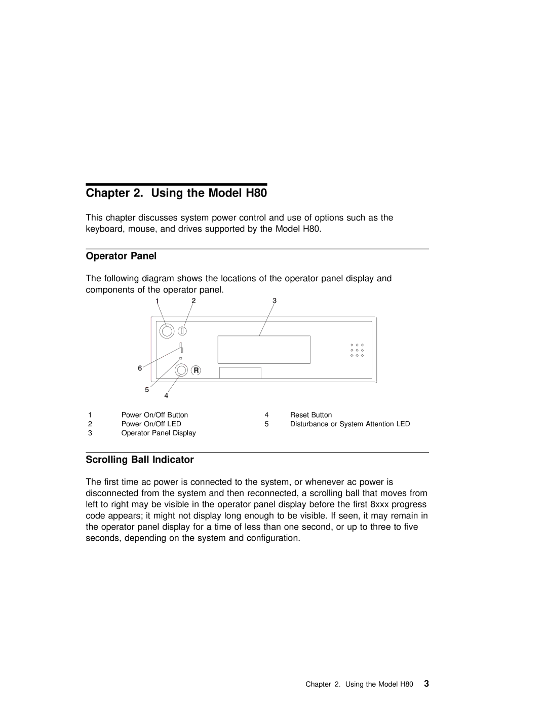
The following | diagram | shows the locations of the operator panel display and | ||||||
components | of | the | operator | panel. |
|
| ||
|
|
| 1 | 2 |
| 3 |
|
|
| 6 |
| R |
|
|
|
|
|
|
| |
|
| 5 |
|
|
|
|
| 4 |
|
|
|
1 | Power | On/Off | Button | 4 | Reset Button |
2 | Power | On/Off | LED | 5 | Disturbance or System Attention LED |
3 | Operator Panel | Display |
|
| |
Scrolling Ball Indicator
The first time ac power is connected to the system, or whenever ac power is
disconnected from | the | system and | then | reconnected, a | scrolling ball that moves fro | ||||||
left | to | right | may | be | visible | in | the | operator | panel | display before the first 8 | |
code | appears; | it | might not display long enough to be | visible. If seen, it may | |||||||
the | operator | panel | display | for | a | time of less | than | one second, or up to three | |||
seconds, | depending | on | the | system | and | configuration. |
| ||||
Chapter 2. Using the Model3 H80