!WARNING
Prolonged or improper use of a computer workstation may pose a risk of serious injury. To reduce your risk of injury, set up and use the computer in the manner described in Appendix A, Setting Up a Healthy Work Environment.
This chapter highlights system hardware and software, and describes the security features of the system.
Front Features
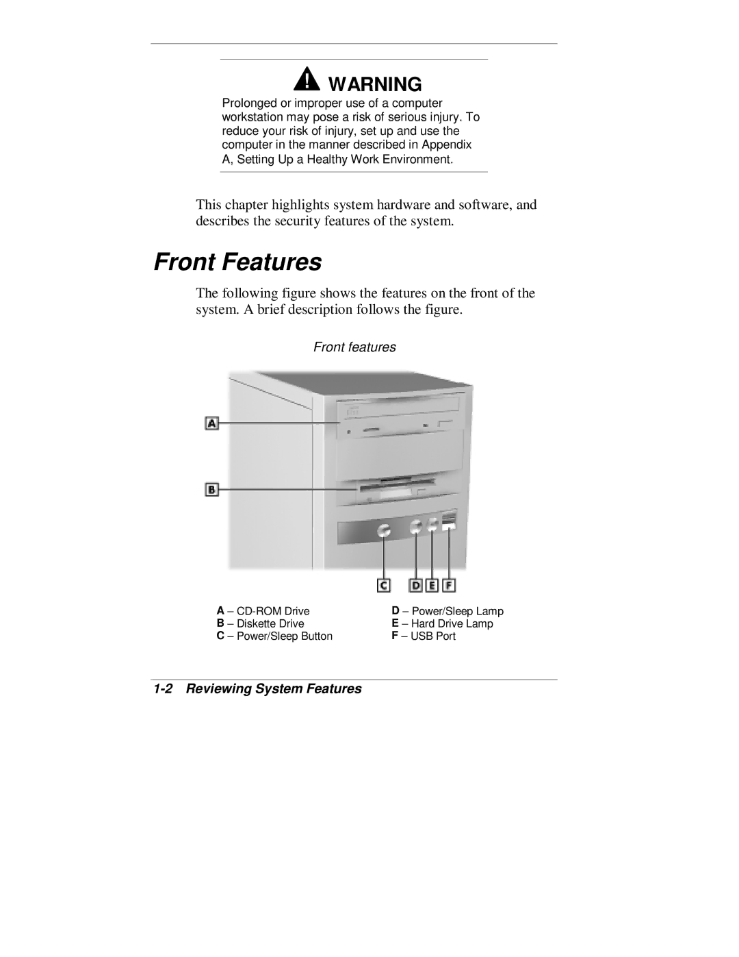
The following figure shows the features on the front of the system. A brief description follows the figure.
Front features
A – | D – Power/Sleep Lamp |
B – Diskette Drive | E – Hard Drive Lamp |
C – Power/Sleep Button | F – USB Port |