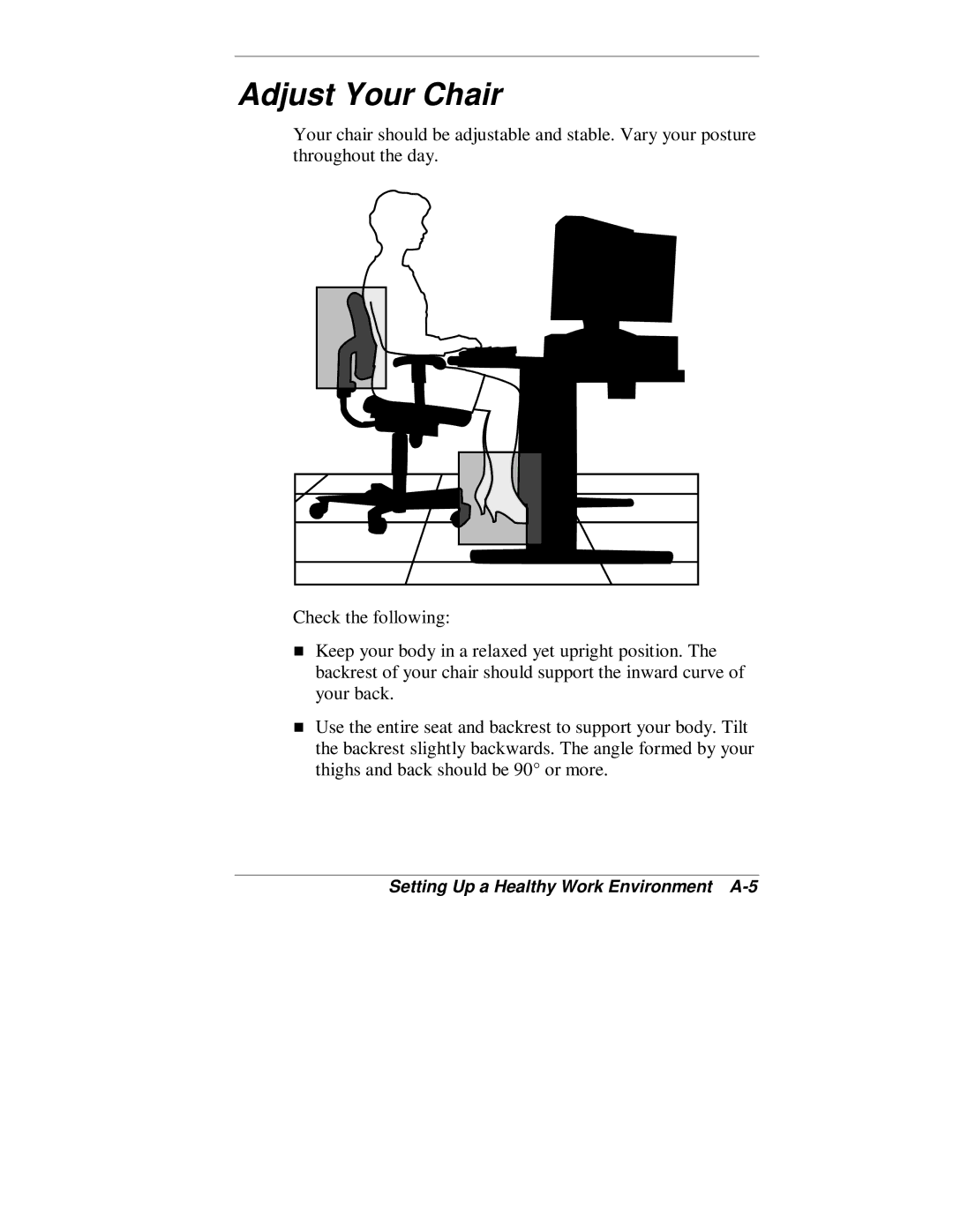
Page
Proprietary Notice and Liability Disclaimer
Using This Guide
Contents
1 Reviewing System Features
Contents
iv Contents
2 Setting Up the System
3 Configuring the System
Contents
4 Installing Options
vi Contents
5 Solving System Problems
6 Getting Services and Support
Contents
A Setting Up a Healthy Work Environment
B System Specifications
viii Contents
Index
Using This Guide
Tdescribes how to access the services
Text Conventions
NEC PowerMate VT 300 Series Release Notes
NEC PowerMate VT 300i Series Quick Setup/Quick
Related Documents
Reference
NEC Help Center
TSpeakers System Features
Reviewing System Features
Front Features Rear Features Inside Features
1-2Reviewing System Features
Front Features
System Controls and Lamps
Universal Serial Bus Port
Diskette Drive A
DVD-ROMDrive
Tape Backup Unit
CD-ROMDrive
PC Card Adapter
Zip Drive
LS-120SuperDisk Drive
1-6Reviewing System Features
Rear features
Rear Features
Reviewing System Features
A – Power Socket
External Connectors
TAudio connectors
Power Supply Features
Inside Features
System Board
Network Board
Chassis
Modem Board
Storage Device Support
Hardware
System Features
Speakers
Preloaded Operating System
Software
Microsoft Internet Explorer
NEC OS Restore CD
NEC Application and Driver CD
Security
Windows network security features
Power-SavingOperation
Setting Up the System
Cable Connections Startup Shutdown
TSystem Care More Information
Cable Connections
Setting Up the System
Startup
Shutdown
Power-SavingOperation
Protecting Your System From Damage
System Care
Tcomponents to temperature variations and stress
Keeping Your System in Good Condition
Moving or Shipping Your System
More Information
Configuration Tools and Utilities
Configuring the System
BIOS Setup Utility Flash Utility
NEC OS Restore CD NEC Application and Driver CD
Configuration Tools and Utilities
Configuring the System
Configuration Tools and Utilities
Configuration
Method, Tool, or Utility
3-4Configuring the System
Configuration Tools and Utilities
Configuration
Method, Tool, or Utility
BIOS Setup Utility
How to Start BIOS Setup
Main Menu
How to Use BIOS Setup
Configuring the System
Navigation Keys
Settings default is bold
3-8Configuring the System
Main Menu Items
Menu Item
Settings default is bold
Configuring the System
Main Menu Items
Menu Item
Settings default is bold
3-10Configuring the System
Main Menu Items
Menu Item
Advanced Menu
3-12Configuring the System
Advanced Menu - Advanced CMOS Setup
Settings default is bold
Menu Item
Advanced Menu - Advanced Chipset Setup
Advanced Menu - Advanced CMOS Setup
Configuring the System
Settings default is bold
3-14Configuring the System
Advanced Menu - Power Management Setup
Settings default is bold
Menu Item
Configuring the System
Advanced Menu - Power Management Setup
Settings default is bold
Restore on AC/Power Loss
Advanced Menu - Peripheral Setup
Advanced Menu - PCI/Plug and Play Setup
3-16Configuring the System
Settings default is bold
Configuring the System
Advanced Menu - Peripheral Setup
Settings default is bold
Menu Item
Advanced Menu - Change Language Setting
Security Menu
3-18Configuring the System
Security Menu Items
Exit Menu Items
Exit Menu
Configuring the System
FLASH Utility
Choosing a Restore Program
NEC OS Restore CD
Introducing OS Restore Options
Launching the NEC OS Restore CD
“Auto Rebuild and Restore”
Auto Rebuild and Restore
5.Click Continue. The following take place
Custom Rebuild and Restore
Click Back to return to the Operating Mode screen
8.Click Continue. The following takes place
Fixing the Operating System
4.Remove the CD from the CD tray
Launching the Application and Driver CD
NEC Application and Driver CD
Installing Software
NEC Help Center
Installing the NEC Help Center
Uninstalling the NEC Help Center
Resolutions for NEC VistaScan USB Monitors
System Board Jumper Settings
You forgot your password and need to clear it
Processor Jumper Settings
3-38Configuring the System
Clear CMOS/Password
5.Move the jumper back to pins 1 and
Power On Mode
5.Replace the left side cover see “Replacing the Left Side Cover” in Chapter 4. Connect system power cables and external options
General Rules Safety Precautions
Installing Options
System Unit Covers System Board Options
TExpansion Boards Data Storage Devices
General Rules
Installing Options
Safety Precautions
System Unit Covers
Removing the Left Side Cover
Removing the left side cover
4-6Installing Options
Replacing the Left Side Cover
Replacing the left side cover
4-8Installing Options
A – Tab Slots
B – Left Side Cover
Removing the Right Side Cover
7.Remove the cover from the chassis
Replacing the Right Side Cover
System Board Options
System board sockets and connectors
Memory Upgrade
the speed of the DIMMs must match or exceed the
Sample DIMM Upgrade Paths
Checking System Memory
Total
Memory
4-16Installing Options
Removing a DIMM
Use the following steps to install a memory module
Installing a DIMM
Inserting a DIMM
4-18Installing Options
A – Plastic Clips
B – Notches
Processor Upgrade
4-20Installing Options
Removing a Celeron or Pentium III Processor
C – Processor Cartridge
A – Locking Lever
B – Universal Retention Mechanism
4-22Installing Options
A – Processor Cartridge
Installing the Celeron or Pentium III processor
B – Retention Mechanism
D – Key
4-24Installing Options
Removing the Pentium II Processor
4.If necessary, remove the AGP graphics board and any other expansion boards blocking access to the processor see “Removing the AGP Graphics Board” or see “Removing an Expansion Board” later in this chapter
4-26Installing Options
Installing the Pentium II Upgrade Processor
Tthe flat side of the bottom bar
4-28Installing Options
Installing the Pentium II processor
Expansion Boards
Locating expansion board slots and connectors
Locating Expansion Slots and Connectors
4-30Installing Options
E – AGP Board Connector
Installing an Expansion Board
4-32Installing Options
Installing an expansion board
Removing the AGP Graphics Board
AGP Board
Removing an Expansion Board
Installing the AGP Graphics Board
Locating Device Bays
Data Storage Devices
tape drive, CD-ROMdrive, or DVD-ROMdrive
Preparing the Device
Connecting Device Cables
4-38Installing Options
System board cable connectors
Installing Options
IDE Connector Configuration
Configuration
Primary connector
4-40Installing Options
Diskette Drive Signal Cable
IDE Connector Configuration
Cabling Storage Devices
IDE Signal Cables
System Power Cables
Use the following procedure to cable an IDE drive
IDE Drive Cabling
Cable a diskette drive as follows
Diskette Drive Cabling
PC Card Adapter Cabling
Cable the network board for Wake-OnLAN as follows
Network Board Wake-OnLAN Cabling
Removing the Front Panel
Installing Storage Devices
Removing the front panel
4-46Installing Options
Tshield
Replace the front panel as follows
Installing a 3 1/2-InchHard Drive
Replacing the Front Panel
4.If you are replacing a hard drive
4-50Installing Options
Installing a hard drive
Installing a 5 1/4-InchDevice
Inserting a device
4-52Installing Options
Solutions to Common Problems
Solving System Problems
How to Clean the Mouse
TBattery Replacement How to Get Help
System Problems
Solutions to Common Problems
Tdealer or the NEC CSD Technical Support Center
Diskette Drive Problems
Monitor Problems
Keyboard/Mouse Problems
CD-ROMDrive Problems
Speaker Problems
How to Clean the Mouse
5.Clean the mouse as follows
Battery Replacement
5-12Solving System Problems
Locating the battery socket on the system board
8.Connect external peripherals and power cables
Help From Your NEC CSD Dealer
How to Get Help
Help From Your Company
Help From NEC CSD Technical Support Center
5-16Solving System Problems
NEC CSD Warranty/Non-WarrantyRepair Service
NEC CSD Website NEC CSD FTP Site
Getting Services and Support
Email/Fax Technical Support Service
6-2Getting Services and Support
NEC CSD Website
NEC CSD FTP Site
Email/Fax Technical Support Service
NEC CSD Bulletin Board System
Log onto the BBS as follows
1.Press Enter to continue
NEC CSD Technical Support Services
Arrange Your Equipment Adjust Your Chair
Setting Up a Healthy Work Environment
Adjust Your Input Devices Adjust Your Monitor
Making Your Computer Work for You
A-2Setting Up a Healthy Work Environment
Making Your Computer Work for You
Setting Up a Healthy Work Environment A-3
A-4Setting Up a Healthy Work Environment
Arrange Your Equipment
Adjust Your Chair
A-6Setting Up a Healthy Work Environment
Adjust Your Input Devices
Tfingers sideways
Adjust Your Monitor
Use a document holder placed close to the screen
Vary Your Workday
A-12Setting Up a Healthy Work Environment
Pre-existingConditions and Psychosocial Factors
Checking Your Chair
Checking Your Comfort: How Do You Measure Up?
Checking Your Keyboard
Checking Your Mouse
Checking You
Peripherals Dimensions Power
System Specifications
System Processor Memory RAM, Cache, ROM
Calendar Clock Input/Output I/O Facilities
Processor Support
System Processor
Intel Celeron Processors
Intel Pentium II Processors
Cache Memory
Random Access Memory RAM
Read Only Memory ROM
Secondary Cache
Calendar Clock
Input/Output I/O Features
Video Memory
Fax/Modem Board
Sound System
Peripherals
Network Board
Diskette Drive
AGP Graphics Board
DVD-ROMDrive
Hard Drive
CD-ROMDrive
PC Card Adapter
Tape Backup Unit
Zip Drive
Supports mixed voltage 3V cards
Power
Dimensions
Operating Environment
Speakers
Compliance
Index-1
Index
Index-2
Index-3
Index-4
Index-5
Index-6
Index-7
Index-8
Radio Frequency Interference Statement
For United States Use Only
Federal Communications Commission
Battery Disposal
Battery Replacement
DECLARATION OF CONFORMITY
POWERMATE VT
We, the Responsible Party
declare that the product