Series L3 Managed Switch Reference Manual for Software
Technical Support
Canadian Department of Communications Compliance Statement
Page
Contents
Chapter Quick Startup
Page
Viii Contents
Page
Page
Security Commands
System Utilities
Chapter Routing Commands
Xiv Contents
Contents
Chapter CLI Commands Differentiated Services
Contents Xvii
Chapter ACL Commands
Appendix a Cabling Guidelines
Index
Organization of This Manual
About this Manual
Special Message Formats
Typographical Conventions
Html version of this manual
How to Navigate this Manual
How to Print this Manual
Chapter
Switch Management Overview
Comparing Switch Management Methods
Setting Up Your Switch Using Direct Console Access
Administration Console Telnet Interface
Connection Description
Connection Settings
Introduction to the Command Menu Interface
ESC
Chapter Web-Based Management Interface
GSM73xx IP address in browser address bar
How to Log In to the GSM73xx
Web-Based Management Utility Introduction
User name/password dialog box
GSM7312 System information
Interactive Switch Image
Menus
GSM7324 Interactive switch image
System-Wide Popup Menus
Switch popup menus
Port-Specific Popup Menus
10 Switch popup menus
Series L3 Managed Switch Reference Manual for Software
Config lag deleteport is the command name
CLI Command Format
Config network parms is the command name
Example 2 config syslocation location
CLI Command Conventions
CLI Command Values
MacAddr
CLI Annotations
Series L3 Managed Switch Reference Manual for Software
Software Version Information
Quick Starting the Switch
User Account Management
Physical Port Data
IP Address
Config users passwd user
Switch Image on
Uploading from Switch to Out-of-Band PC Only Xmodem
Traplog trap log
Downloading from Out-of-Band PC to Switch Only Xmodem
Downloading from Tftp Server
Factory Defaults
Port Routing, RIP, and Ospf Configuration
Basic Configuration Examples
RIP and Ospf Vlan Routing
11. Ospf Configuration Example
Series L3 Managed Switch Reference Manual for Software
This example creates two router ports to run Ospf
Creating the VLANs
Vlan Example
Solution
Show inventory
System Information and Statistics Commands
Text used to identify the product name of this switch
Show inventory
Show sysinfo
Config sysname
Config syslocation
Show sysinfo
Show forwardingdb table
Config syscontact
Show arp switch
Show arp switch
Show stats port detailed
Show stats port detailed slot.port
Packets Received 64 Octets The total number of packets
Series L3 Managed Switch Reference Manual for Software
Packets Received with
Series L3 Managed Switch Reference Manual for Software
Broadcast Packets Transmitted The total number of packets
Packets Transmitted 256-511 Octets The total number
Packets Transmitted 512-1023 Octets The total number
Multicast Packets Transmitted The total number of packets
802.3x Pause Frames Received a count of MAC Control
Show stats port summary slot.port
Show stats port summary
Show stats switch detailed
Show stats switch detailed
Series L3 Managed Switch Reference Manual for Software
Line number of the event
Show stats switch summary
Show eventlog
File in which the event originated
Event code
Show msglog
Show traplog
Task ID of the event
Show network
Management Commands
Config network parms
Config network protocol
Show serial
Config network webmode
Config network javamode
Config prompt
9600
Config serial baudrate
Config serial timeout
Config snmpcommunity accessmode
Config snmpcommunity ipmask
Config snmpcommunity create
Config snmpcommunity delete
Config snmpcommunity ipaddr
Config snmpcommunity mode
Config snmptrap create
Show snmptrap
Show trapflags
Config snmptrap delete
Config snmptrap ipaddr
Config snmptrap mode
Config trapflags authentication
Config trapflags bcaststorm
Config trapflags linkmode
Show telnet
Config trapflags multiusers
Config trapflags stpmode
Config telnet maxsessions
Show forwardingdb agetime fdbidall
Config telnet mode
Config telnet timeout
Show forwardingdb agetime
Config switchconfig broadcast
Device Configuration Commands
Config forwardingdb agetime
Show switchconfig
Able
Config switchconfig flowcontrol
Show port
Config port adminmode
Config port autoneg
Config port linktrap
Config port physicalmode
Config port lacpmode
Show lag logical slot.portall
Config lag create
Config lag addport
Show lag
Config lag name
Config lag deleteport
Config lag adminmode
Config lag linktrap
Show vlan summary
Config lag deletelag
Config lag stpmode
Show vlan summary
Show vlan detailed
Config vlan detailed vlan id, where the ID is a
Config vlan makestatic
Config vlan create
Config vlan delete
Config vlan name
Config vlan participation
Config vlan port tagging
Show vlan port
Config vlan port pvid
Config vlan port acceptframe
Admit All
Config vlan port acceptframe allvlan
Config vlan port ingressfilter
Config protocol create
Config protocol delete
Config protocol vlan remove
Config protocol protocol add
Config protocol protocol remove
Config protocol vlan add
Show garp interface
Config protocol interface add
Config protocol interface remove
Show garp info
Specifies the interval between the transmission of Garp PDUs
Config garp gvrp interfacemode
Config garp gmrp adminmode
Config garp gmrp interfacemode
Config garp gvrp adminmode
Config garp jointimer
Config garp leavetimer
Config garp leavealltimer
Show igmpsnooping
Config igmpsnooping adminmode
Config igmpsnooping interface mode
Config igmpsnooping groupmembershipinterval
Config igmpsnooping maxresponse
Config igmpsnooping mcrtrexpiretime
Show mfdb gmrp
Show mfdb table
Show mfdb staticfiltering
Show mfdb igmpsnooping
Show mirroring
Config mirroring create
Show mfdb stats
Show mirroring
Config mirroring delete
Config mirroring mode
Show macfilter
Config macfilter create
Config macfilter remove
Config macfilter addsrc
Config macfilter delsrc
Config macfilter adddest
Config macfilter deldest
Show spanningtree summary
Spanning Tree Commands
Config spanningtree adminmode
Config spanningtree forceversion
Config spanningtree configuration name
Config spanningtree configuration revision
Config spanningtree port bpdumigrationcheck
Show spanningtree port
Show spanningtree bridge
Config spanningtree port mode
Config spanningtree bridge maxage
Config spanningtree bridge hellotime
Config spanningtree bridge forwarddelay
Config spanningtree bridge priority
Show spanningtree cst detailed
Show spanningtree cst port detailed
Show spanningtree cst port summary
128
Config spanningtree cst port pathcost
Config spanningtree cst port priority
Auto
Config spanningtree mst vlan add
Config spanningtree cst port edgeport
Config spanningtree mst create
Config spanningtree mst delete
Config spanningtree mst port priority
Config spanningtree mst vlan remove
Config spanningtree mst priority
Config spanningtree mst port pathcost
Instance
List of multiple spanning trees IDs currently configured
Show spanningtree mst summary
Show spanningtree mst detailed
Show spanningtree mst port detailed
Show spanningtree mst port summary
Show spanningtree vlan vlan
User Account Management Commands
Show spanningtree vlan
Show users
Config users snmpv3 authentication
Config users add
Config users passwd
Config users delete
Config users snmpv3 encryption
Config users snmpv3 accessmode
Show loginsession
Config radius timeout
Security Commands
Config loginsession close
Config radius maxretransmit
Config radius accounting mode
Config radius accounting server add
Config radius accounting server port
Config radius server port
Config radius accounting server remove
Config radius accounting server secret
Config radius server add
Config radius server msgauth
Config radius server remove
Config radius server secret
Config radius server primary
Show radius server stats
Secret Configured
Show radius summary
Show radius server summary
Show radius accounting summary
Configured IP address of the accounting server
Show radius accounting stats
Port in use by the accounting server
Yes or No
Show radius stats
Config dot1x adminmode
Config dot1x port initialize
Config dot1x port reauthenticate
Config dot1x port controldir
Config dot1x port controlmode
Config dot1x port quietperiod
Config dot1x port maxrequests
Config dot1x port transmitperiod
Config dot1x port supptimeout
Config dot1x port servertimeout
Show dot1x port summary
Config dot1x port reauthenabled
Sible values are Enabled and Disabled
Show dot1x summary
Interface whose configuration is displayed
Show dot1x port stats
Config authentication login create
Config authentication login delete
Clear dot1x port stats
Config dot1x port users add
Config authentication login set
Config dot1x defaultlogin
Config dot1x login
Show authentication login info
Config dot1x port users remove
Config users defaultlogin
Config users login
Show dot1x port users
Show authentication login users
Show users authentication
System Utilities
Transfer upload serverip
Save config
Transfer upload mode
Logout
Transfer upload datatype
Transfer upload filename
Transfer download path
Transfer download mode
Transfer upload start
Transfer download serverip
Clear transfer
Transfer download filename
Transfer download datatype
Transfer download start
Clear vlan
Clear config
Clear pass
Clear traplog
Ping
Clear stats switch
Reset system
Clear igmpsnooping
Series L3 Managed Switch Reference Manual for Software
Routing Commands
Show arp table
Show arp table
Config arp delete
Config arp agetime
Config arp cachesize
Config arp create
Config arp retries
Show ip interface
Show ip interface slot.port
Are Ethernet or Snap
Config interface encaps
Config interface routing
Config ip interface mtu
Enable
Config ip interface netdirbcast
Config ip interface create
Config ip interface delete
Show ip vlan
Config ip forwarding
Config routing
Show ip stats
Show router ip interface summary
Config ip vlan routing create
Config ip vlan routing delete
Show router ip interface summary
Show router ospf info
Config router id
Config router id routerid
Show router ospf info
Config router ospf preference
Config trapflags ospf
Config router ospf adminmode
Config router ospf asbr
Show router ospf interface stats
Show router ospf interface summary
Config router ospf interface areaid
Config router ospf interface authtypekey
Config router ospf interface interval dead
Config router ospf interface mode
Config router ospf interface interval hello
Config router ospf interface interval retransmit
Config router ospf interface iftransitdelay
Which is the highest router priority
Config router ospf interface priority
Config router ospf interface cost
Show router ospf area info
Show router ospf area range
Config router ospf area range create
Config router ospf area stub summarylsa
Config router ospf area range delete
Config router ospf area stub metric value
Config router ospf area stub metric type
Show router ospf neighbor detailed
Config router ospf area stub create
Config router ospf area stub delete
Config router ospf area delete
Show router ospf neighbor table
Show router ospf lsdb summary
Show router ospf stub table
Show router ospf lsdb summary
Show router ospf stub table
Show router rip interface detailed
Show router rip info
Show router rip interface detailed
Show router rip info
Config router rip adminmode
Show router rip interface summary
Show router rip interface summary
Default password key is an empty string. Unauthenticated
Config router rip preference
Config router rip interface authtypekey
Config router rip interface defaultmetric
Both
Config router rip interface mode
Config router rip interface version receive
Config router rip interface version send
Is the neighbor interface of the Ospf virtual interface
Config router ospf virtif create
Show router ospf virtif detailed
Show router ospf virtif summary
Config router ospf virtif interval dead
Config router ospf virtif delete
Config router ospf virtif authtypekey
Config router ospf virtif transdelay
Config router ospf extlsdblimit
Config router ospf virtif interval hello
Config router ospf virtif interval retransmit
Config router ospf exoverflowinterval
Show router route table
Show router route table
Show router route bestroutes
Show router route entry
Show router route preferences
Config router route create
Config router route default delete
Config router route delete
Config router route preference
Config router route default create
Config router vrrp adminmode
Show router vrrp interface detailed
Show router vrrp interface summary
Represents the router ID of the virtual router
Is the IP Address that was configured on the virtual router
Represents the state Master/backup of the virtual router
Show router vrrp interface stats
There is no default value for vrID
Config router vrrp interface adminmode
Config router vrrp interface routerID
Config router vrrp interface priority
Config router vrrp interface authdetails
Config router vrrp interface ipaddress
Config router vrrp interface preemptmode
Config router vrrp interface advinterval
Config router rtrdiscovery mininterval
Config router vrrp removedetails
Config router rtrdiscovery adminmode
Config router rtrdiscovery maxinterval
Show router rtrdiscovery
Config router rtrdiscovery lifetime
Config router rtrdiscovery address
Config router rtrdiscovery preference
Show router bootpdhcprelay
Config router bootpdhcprelay circuitidoptionmode
Config router bootpdhcprelay adminmode
Config router bootpdhcprelay maxhopcount
Config router bootpdhcprelay minwaittime
Config router bootpdhcprelay serverip
Series L3 Managed Switch Reference Manual for Software
CLI Commands Differentiated Services
Config diffserv adminmode
General Commands
Config diffserv class create acl
Class Commands
Config diffserv class create all
Config diffserv class create any
Config diffserv class delete
None
Config diffserv class rename
Config diffserv class match cos
Config diffserv class match dstip
Config diffserv class match dstl4port number
Config diffserv class match dstl4port keyword
Config diffserv class match dstl4port range
Config diffserv class match dstmac
Config diffserv class match every
Config diffserv class match ipprecedence
Config diffserv class match ipdscp
Config diffserv class match iptos
Config diffserv class match protocol number
Config diffserv class match protocol keyword
Config diffserv class match srcip
Config diffserv class match refclass
Config diffserv class match srcl4port number
Config diffserv class match srcl4port keyword
Config diffserv class match srcl4port range
Config diffserv class match srcmac
Config diffserv class match vlan
Config diffserv policy create
Policy Commands
Config diffserv policy class remove
Config diffserv policy delete
Config diffserv policy rename
Config diffserv policy class add
Config diffserv policy bandwidth percent
Config diffserv policy bandwidth kbps
Bandwidth all forms, Shape Peak
Config diffserv policy expedite kbps
Config diffserv policy expedite percent
Config diffserv policy mark cos
Out
Mark IP Precedence, Police all forms
Config diffserv policy mark ipdscp
Config diffserv policy mark ipprecedence
Config diffserv policy police action conform drop
Config diffserv policy police action conform markdscp
Config diffserv policy police action conform markprec
Config diffserv policy police action conform send
Config diffserv policy police action exceed markdscp
Config diffserv policy police action exceed drop
Config diffserv policy police action exceed markprec
Config diffserv policy police action exceed send
Config diffserv policy police action nonconform drop
Config diffserv policy police action nonconform markdscp
Config diffserv policy police action nonconform markprec
Config diffserv policy police action nonconform send
Mark IP DSCP, Mark IP Precedence
Config diffserv policy police style simple
Config diffserv policy police style singlerate
Allowed for a given class instance in a particular policy
Config diffserv policy police style tworate
Config diffserv policy shape average
Config diffserv policy randomdrop
Applied
Service Commands
Config diffserv policy shape peak
Neither of the shaping rate parameters is allowed to exceed
Config diffserv service add
Config diffserv service remove
Particular direction at any one time
Show diffserv class detailed
Show Commands
Show diffserv info
Show diffserv class summary
Policy type, namely whether it is an inbound or outbound
Current number of entries rows in the Service Table
Show diffserv policy detailed
Name of this policy
Denotes the mark/re-mark value used as the Dscp for traffic
Show diffserv policy summary
Show diffserv service info summary
Show diffserv service info detailed
Show diffserv service stats detailed
Slot number and port number of the interface slot.port
Direction
Name of this class instance
Show diffserv service stats summary
Series L3 Managed Switch Reference Manual for Software
Show acl detailed
Show acl summary
Config acl rule create
Config Commands
Config acl create
Config acl delete
Config acl rule match dstl4port keyword
Config acl rule delete
Config acl rule action
Config acl rule match dstip
Config acl rule match dstl4port range
Config acl rule match every
Config acl rule match ipdscp
Config acl rule match iptos
Config acl rule match ipprecedence
Config acl rule match protocol keyword
Config acl rule match protocol number
Config acl rule match srcip
Config acl rule match srcl4port keyword
Config acl rule match srcl4port range
Config acl interface add
Config acl interface remove
Fast Ethernet Cable Guidelines
Appendix a Cabling Guidelines
Category 5 Cable
Category 5 Cable Specifications
Twisted Pair Cables
Specifications Category 5 Cable Requirements
Figure A-2illustrates crossover twisted pair cable
Patch Panels and Cables
Cabling
Using 1000BASE-T Gigabit Ethernet over Category 5 Cable
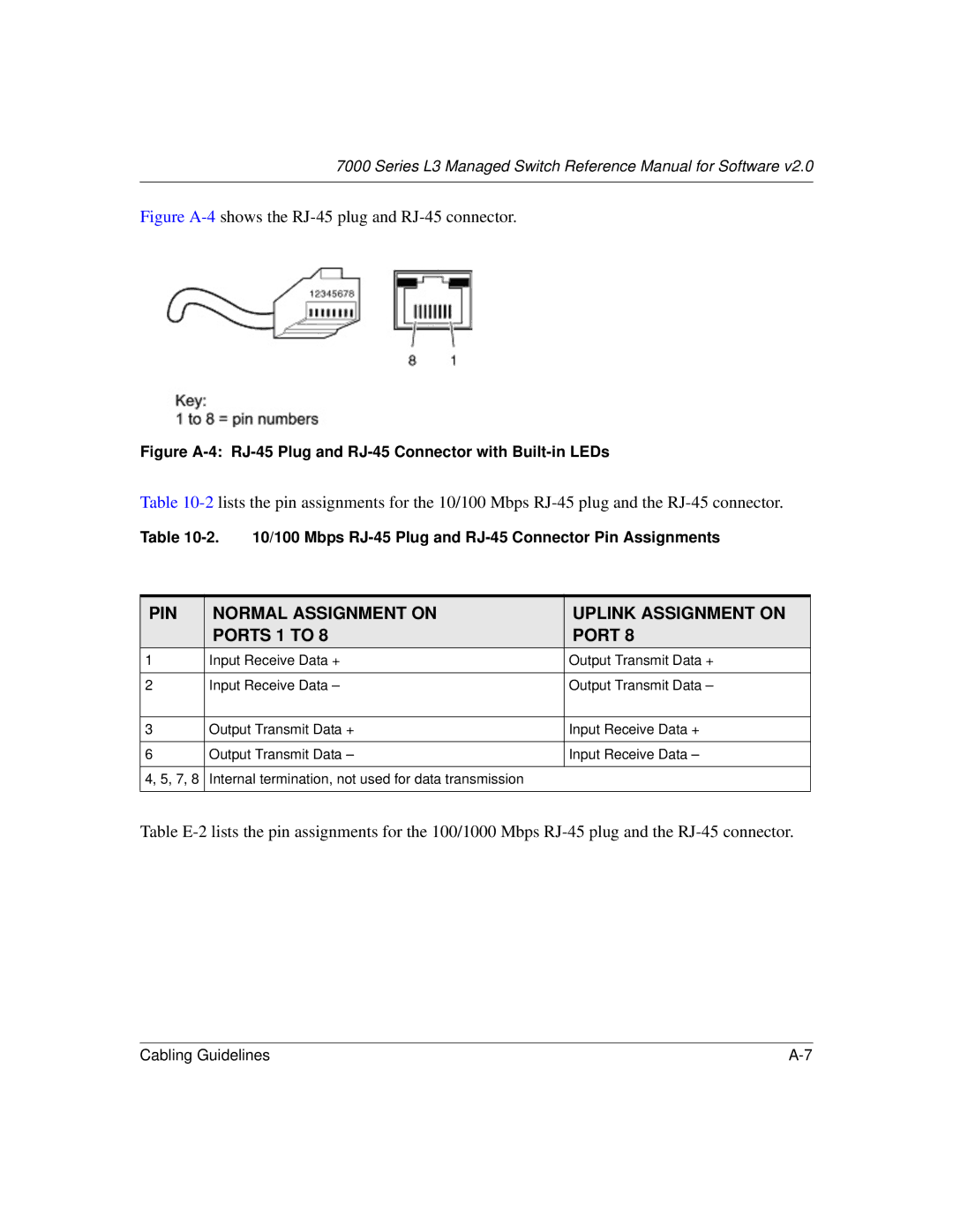
RJ-45 Plug and RJ-45 Connectors
Near End Cross Talk Next
Patch Cables
PIN Normal Assignment on Uplink Assignment on Ports 1 to
Conclusion
Appendix B 802.1x Port-Based Authentication Overview
Figure B-1 802.1x authentication
Series L3 Managed Switch Reference Manual for Software
Series L3 Managed Switch Reference Manual for Software
Numeric
Appendix C Glossary
See Area Border Router on
See Application Programming Interface on
See Bridge Protocol Data Unit on
Packet sent to all devices on a network
See Command Line Interface on
See Device Application Programming Interface on
See Distance-Vector Multicast Routing Protocol. on
Computer, printer, or server that is connected to a network
See Generic Attribute Registration Protocol. on
See Garp Information Propagation on
See Internet Group Management Protocol on
See Joint Test Action Group on
MAC
Megabits per second
See Multiplexing on
See Network Address Translation on
See Operating System Application Programming Interface on
See Protocol Independent Multicast Dense Mode on
See Quality of Service on
See Routing Information Protocol on
Model of Serial Management Controller from Motorola
Static Random Access Memory
See TLS on
An abbreviation that represents Unit, Slot, Port
Models
Series L3 Managed Switch Reference Manual for Software
Series L3 Managed Switch Reference Manual for Software
Index
Index
Gvrp
Index
Index
STP
Xmodem