A
System Overview Configurations
Simple Failover Configuration
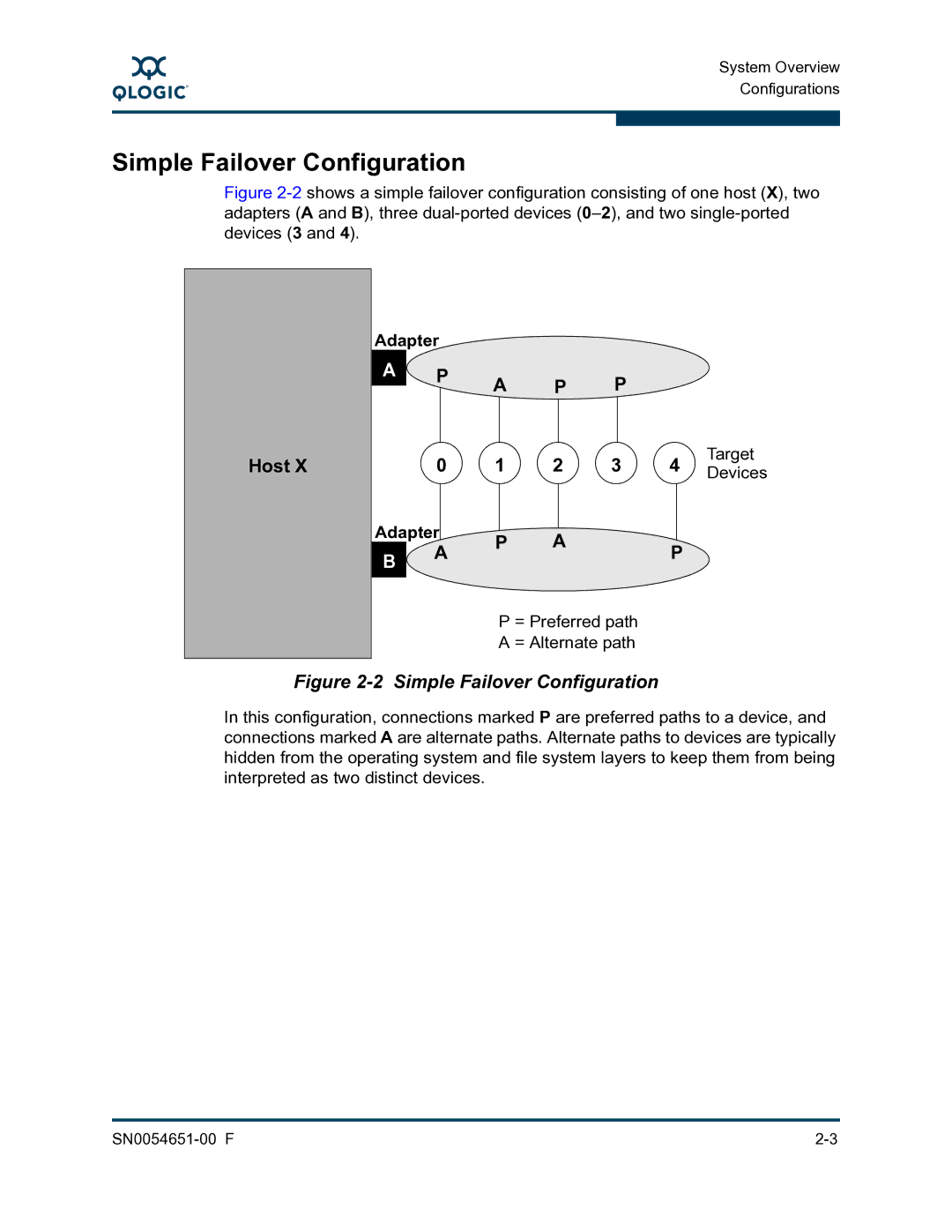
Figure 2-2 shows a simple failover configuration consisting of one host (X), two adapters (A and B), three dual-ported devices (0–2), and two single-ported devices (3 and 4).
Host X
Adapter
A | P | A | P |
| P |
| Target |
|
|
|
| ||||
| 0 | 1 | 2 | 3 | 4 | ||
| Devices | ||||||
Adapter | P | A |
|
| P |
| |
B | A |
|
|
| |||
|
|
|
|
| |||
|
|
|
|
|
|
| |
|
| P = Preferred path |
|
| |||
|
| A = Alternate path |
|
| |||
Figure 2-2 Simple Failover Configuration
In this configuration, connections marked P are preferred paths to a device, and connections marked A are alternate paths. Alternate paths to devices are typically hidden from the operating system and file system layers to keep them from being interpreted as two distinct devices.