Front and reat panels
Rear panel
SCSI | MIDI | DIGITAL (5,6) | FOOT PHONES |
| INPUT B |
|
|
| INPUT A |
| |
OUT THRU | IN | IN | SWITCH | 4 | 3 | 2 | 1 | 4 | 3 | 2 | 1 |
AC IN |
|
|
|
|
|
|
|
|
|
|
|
|
| OUT |
| B | A | R | L |
|
|
|
|
|
|
|
| AUX SEND | MASTER OUT |
|
|
|
| ||
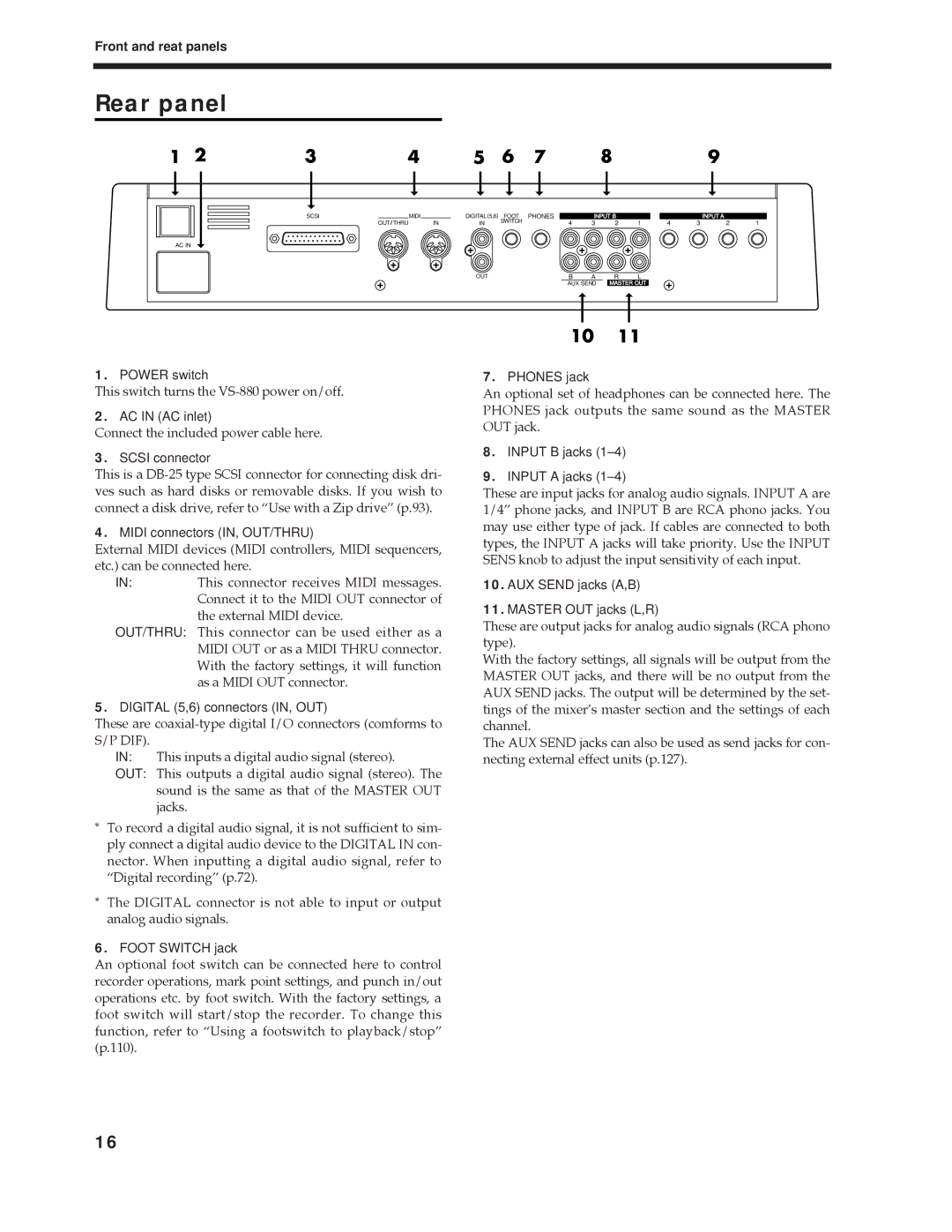
1.POWER switch
This switch turns the
2.AC IN (AC inlet)
Connect the included power cable here.
3.SCSI connector
This is a
4.MIDI connectors (IN, OUT/THRU)
External MIDI devices (MIDI controllers, MIDI sequencers, etc.) can be connected here.
IN:This connector receives MIDI messages. Connect it to the MIDI OUT connector of the external MIDI device.
OUT/THRU: This connector can be used either as a MIDI OUT or as a MIDI THRU connector. With the factory settings, it will function as a MIDI OUT connector.
5.DIGITAL (5,6) connectors (IN, OUT)
These are
IN: This inputs a digital audio signal (stereo).
OUT: This outputs a digital audio signal (stereo). The sound is the same as that of the MASTER OUT jacks.
*To record a digital audio signal, it is not sufficient to sim- ply connect a digital audio device to the DIGITAL IN con- nector. When inputting a digital audio signal, refer to ÒDigital recordingÓ (p.72).
*The DIGITAL connector is not able to input or output analog audio signals.
6.FOOT SWITCH jack
7.PHONES jack
An optional set of headphones can be connected here. The PHONES jack outputs the same sound as the MASTER OUT jack.
8.INPUT B jacks
9.INPUT A jacks
These are input jacks for analog audio signals. INPUT A are 1/4Ó phone jacks, and INPUT B are RCA phono jacks. You may use either type of jack. If cables are connected to both types, the INPUT A jacks will take priority. Use the INPUT SENS knob to adjust the input sensitivity of each input.
10.AUX SEND jacks (A,B)
11.MASTER OUT jacks (L,R)
These are output jacks for analog audio signals (RCA phono type).
With the factory settings, all signals will be output from the MASTER OUT jacks, and there will be no output from the AUX SEND jacks. The output will be determined by the set- tings of the mixerÕs master section and the settings of each channel.
The AUX SEND jacks can also be used as send jacks for con- necting external effect units (p.127).
An optional foot switch can be connected here to control recorder operations, mark point settings, and punch in/out operations etc. by foot switch. With the factory settings, a foot switch will start/stop the recorder. To change this function, refer to ÒUsing a footswitch to playback/stopÓ (p.110).
16