Chapter 2 Before you start (VS-880 terminology)
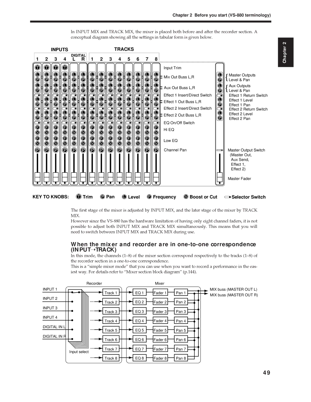
In INPUT MIX and TRACK MIX, the mixer is placed both before and after the recorder section. A conceptual diagram showing all the settings in tabular form is given below.
INPUTS
DIGITAL
1 2 3 4 L R
TRACKS
1 | 2 | 3 | 4 | 5 | 6 | 7 | 8 |
Input Trim |
| |
Mix Out Buss L,R | Master Outputs | |
{ Level & Pan | ||
| ||
Aux Out Buss L,R | Aux Outputs | |
{ Level & Pan | ||
| ||
Effect 1 Insert/Direct Switch | Effect 1 Return Switch | |
Effect 1 Out Buss L,R | Effect 1 Level | |
Effect 1 Pan | ||
Effect 2 Insert/Direct Switch | ||
Effect 2 Return Switch | ||
Effect 2 Out Buss L,R | Effect 2 Level | |
Effect 2 Pan | ||
EQ On/Off Switch | ||
| ||
Hi EQ |
| |
Low EQ |
| |
Channel Pan | Master Output Switch | |
| (Master Out, | |
| Aux Send, | |
| Effect 1, | |
| Effect 2) | |
| Master Fader |
Chapter 2
KEY TO KNOBS: | Trim | Pan | Level | Frequency | Boost or Cut | Selector Switch |
The first stage of the mixer is adjusted by INPUT MIX, and the later stage of the mixer by TRACK MIX.
However since the
When the mixer and recorder are in
In this mode, the channels (1Ð8) of the mixer section correspond respectively to the tracks (1Ð8) of the recorder section in a
This is a Òsimple mixer modeÓ that you can use when you want to record a performance in the eas- iest way. For details refer to ÒMixer section block diagramÓ (p.144).
Recorder | Mixer |
INPUT 1
INPUT 2
INPUT 3
INPUT 4
DIGITAL IN L
DIGITAL IN R
Input select
![]() Track 1
Track 1
![]()
![]() Track 2
Track 2
![]()
![]() Track 3
Track 3
![]()
![]() Track 4
Track 4
![]()
![]() Track 5
Track 5
Track 6
![]()
![]() Track 7
Track 7
![]()
![]() Track 8
Track 8
![]()
![]() EQ 1
EQ 1 ![]() Fader 1
Fader 1 ![]() Pan 1
Pan 1 ![]()
![]()
![]() EQ 2
EQ 2 ![]()
![]() Fader 2
Fader 2 ![]() Pan 2
Pan 2 ![]()
![]()
![]() EQ 3
EQ 3 ![]() Fader 3
Fader 3 ![]()
![]() Pan 3
Pan 3 ![]()
![]()
![]()
![]() EQ 4
EQ 4 ![]()
![]() Fader 4
Fader 4 ![]() Pan 4
Pan 4 ![]()
![]()
![]() EQ 5
EQ 5 ![]() Fader 5
Fader 5 ![]()
![]() Pan 5
Pan 5 ![]()
![]()
![]()
![]() EQ 6
EQ 6 ![]()
![]() Fader 6
Fader 6 ![]() Pan 6
Pan 6 ![]()
![]()
![]() EQ 7
EQ 7 ![]() Fader 7
Fader 7 ![]()
![]() Pan 7
Pan 7 ![]()
![]()
![]()
![]() EQ 8
EQ 8 ![]()
![]() Fader 8
Fader 8 ![]() Pan 8
Pan 8 ![]()
![]() MIX buss (MASTER OUT L) MIX buss (MASTER OUT R)
MIX buss (MASTER OUT L) MIX buss (MASTER OUT R)
49