DK Admin/DK Backup Release User Guide
726+,%$
Publication Information
Contents
Using DKAdmin/DKBackup
Backup Menu DKBackup
Iii
Appendix B DK424 RCTUE/F Upgrade Using DKAdmin
Introduction
Organization
Conventions
Screen Variations
Viii
How To Use This Manual
Related Documentation
How To Use This Manual
Grand Tour
Capabilities
DKAdmin DKBackup
Basic Operations
Main Menu DKAdmin DKBackup File Menu
Main Menu DKAdmin DKBackup
Screen Conventions
Screen Conventions
Screen Conventions
Installing DKAdmin
Check System Requirements
Power Up DKAdmin PC
DKAdmin Hardware Connections
From DOS Only PC
Optional Make Installation Floppy Disks
From Windows
Type copy *.* a or B and press Enter
Install DKAdmin
Windows PC from CD-ROM
Windows PC from Floppy Disks
DOS Only PC from CD-ROM
DOS Only PC from Floppy Disks
Start-up DKAdmin in MS-DOS
Run DKAdmin Program
Start-up DKAdmin under Windows 98, 95 or Windows NT
Run DKAdmin
Set Windows DKAdmin Program Properties
Cmd line C\280ADMIN\DKADMIN.BAT Working C\280ADMIN
Display toolbar Restore settings on startup
Usage Full-screen
Fast ROM emulation Dynamic memory allocation
Connect to the Strata DK Telephone System
Connect to the Strata DK Telephone System
Installing DKBackup
Power Up DKBackup PC
DKBackup Hardware Connections
Optional Make Installation Floppy Disks
Install DKBackup
Enter
Start-up DKBackup in MS-DOS
Run DKBackup Program
Start-up DKBackup under Windows 3.11, 95, 98 or Windows NT
Run DKBackup
Set Windows DKBackup Program Properties
Cmd line C\280BCKUP\DKBCKUP.BAT Working C\280BCKUP
Usage Full-screen
Connect to the Strata DK Telephone System
Connect to the Strata DK Telephone System
To log on to DKAdmin
Using DKAdmin/DKBackup
DKAdmin
Before You Start
Logging On
DKAdmin Main Menu Options
DKBackup
To log on to DKBackup
Keyboard Conventions
Esc
Up/Page Down
System Messages
Using the Pull-Down Menus
Error Messages
On-Line Help
To exit the DKAdmin/DKBackup system
Logging Off
Logging Off
Quick-start Procedures for Using DKAdmin
File Menu
For an Existing Customer
Maintain Customer File
To quickly use DKAdmin with a new installation of Strata DK
To access the Maintain Customer File option
For a New Customer
Message Record exists
Wmau
To modify a customer record
Settings
Select Customer
To delete a customer record
Dial DK
To access the option
To dial a Strata DK to upload/download data
About
Hangup Connection
Transfer DK Data
Exit
Administration Menu DKAdmin
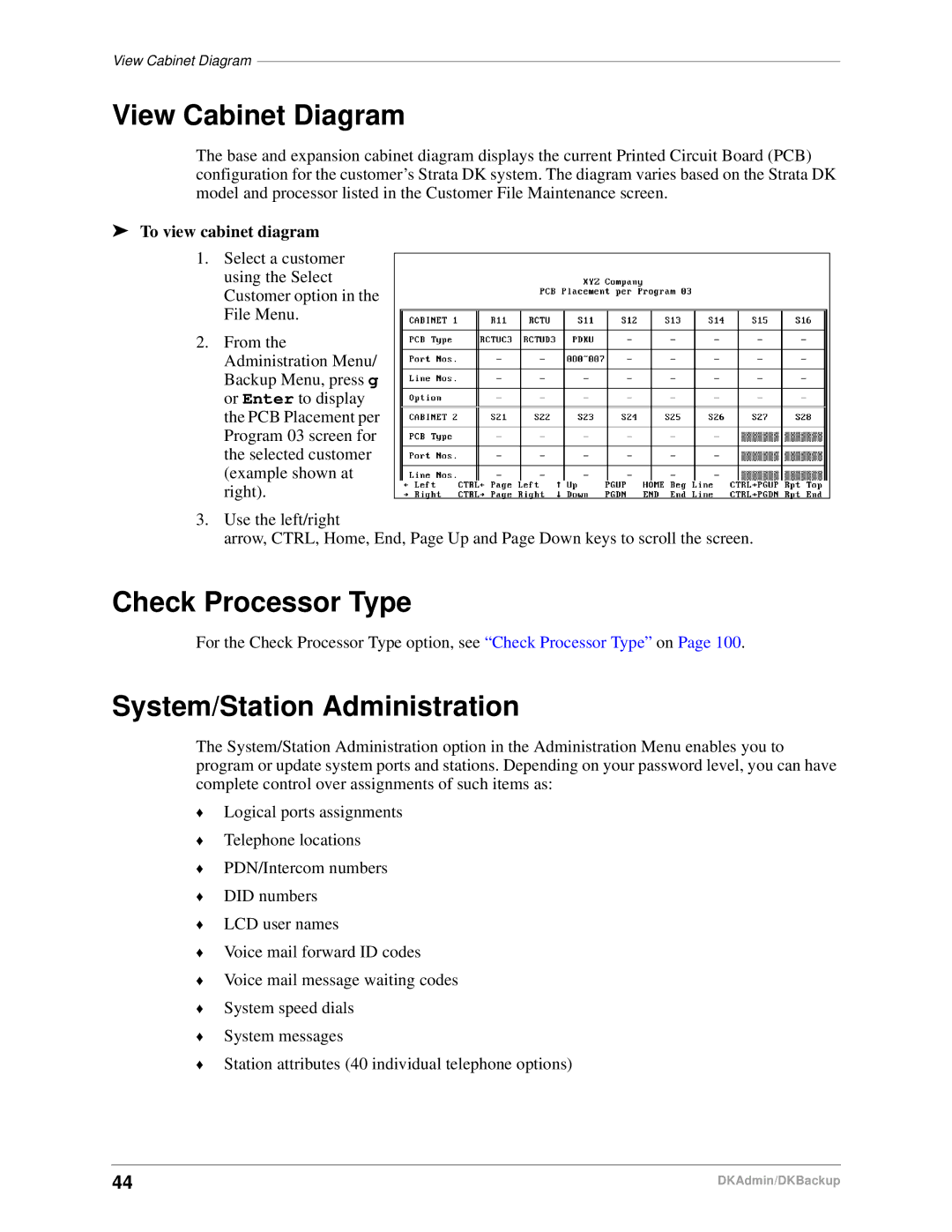
To view cabinet diagram
View Cabinet Diagram
System/Station Administration
Check Processor Type
System/Station Administration
To program or update the entire system or an individual port
Programming/Updating System
Reset To Default Values. Go Ahead?
Printing Port/Station Information F3
To print port and station information
System Speed Dial Number F7
To set or change available system speed dial numbers
Station Port Attributes Ctrl Enter
To program or update individual station port attributes
System LCD Messages F8
To set or change available system LCD messages
See Appendix a Connecting to Strata DK
HS-OCA
Directory
To copy a range of attributes
Ports 000 to
Copy PRG38/PRG39-Flexible Key Assignments Also?
To view or change flexible button assignments
To copy selected keys to selected ports
To view CO line assignments
To assign speed dial assignments
Saving/Uploading Programmed Data F9
To assign system messages
To upload programmed data
Customer Name PCB Placement Per Program 03 Assignments
Printout Examples
Did
Intercom 202/Port 002 Attributes for Brian No
Intercom 202/Port 002 Personal Messages for Brian No
Telephone Flexible Button Assignments
To access flexible button assignments
Flexible Button Programming Section
To change an assigned button
DN Does Not Exist. Please Refer to Program *04
To make assignments to another port
Add-On Module Button Assignments
No Ports Have Add-on Modules. Do You Want To Add a Port?
Port does not have add-on module. Add?
Current template copied from port
To copy the features from one port to another
To change an assigned feature
To clear the port
To reset all keys and return them to their default settings
DSS Console Button Assignments
To assign more than one speed dial number
Attendant Console Flexible Button Assignments
To make assignments to another console or console group
Are you sure you want to reset flexible keys?
To edit your attendant console flexible button assignments
To make assignments to another attendant console
System Speed Dial Numbers
To access speed dial assignments
Speed Dial Programming Section
To edit system speed dial number assignments
Station Speed Dial Numbers
To edit station speed dial number assignments
ACD Programs
ACD Administration
To access ACD administration
To edit ACD programs
To view notes on a program
To use the Strata DK’s program files to edit
ACD Agent Programs
To edit ACD agent programs
Auto Answer and No Auto Answer
Program Administration Section
To access a Strata DK program
View All Programs Download, Edit, Upload
Return to the originally selected program screen
To pull the program data from the DK
To edit a program
This operation will modify DN numbers. Go ahead?
To print programs
Prgall
Security Maintenance Section
To limit the Strata DK programs a user may edit
Program Security Default Levels
Strata DK Program Security Security Level Program Title
Strata DK Program Security
Strata DK Program Security
Auto Attendant Prompt/Station Assignments
Automatic Preference
LCR Schedule Assignments for LCR Plans
CO/Line/Station Ringing Assignments DAY 2 12-Second Delay
Directory Number Administration
Ahead?
To set or change detailed information for the PDNs/PhDNs
To specify your ringing options
To set/change CO Line flexible key assignments
Dnis Administration
DNIS/DID/ANI Line Assignments
To set/change your DNIS/DID/ANI line assignments
Dnis Number/Name/Ringing/VM-ID Assignments
Field Selection
To set/change the Dnis address reference numbers
All ports will be reset to default values. Go ahead?
Dnis Network Table Assignments
Dnis Tenant Lock Assignments
Distributed Hunt Group Administration
To set/change passwords for station port numbers
Upload modified programs to DK now?
Call Forward Assignments
To set/change the call forward assignments
E911/CAMA Trunk Programs R4 Only
To edit E911/CAMA trunk programs
Follow ~ of To edit E911/CAMA trunk programs above
To access Isdn Programs
Isdn Programs R4 Only
To edit Isdn programs
Backup/Restore Data
View/Print Data
Backup Menu DKBackup
To check processor type
Backup Data
100
Prior to backing up
101
DK System Program File
102
Restore Data
To restore upload a customer’s database
Prior to restoring data
103
104
Important! These messages display
105
Baud Rate Selection
106
You will send data to the DK. Are you sure?
Upgrading a Customer’s Processor
Upgrade
Strata DK Processor PCB Upgrade
107
To upgrade the processor
108
109
110
111
Pull Program 03 from DK to Update Customer Database?
112
113
114
To view and print a customer program
115
Please select
To print a customer program
116
Company General Information
System Installation
Options Menu
117
Reset Colors
Screen Type/Color Installation
Screen Mode
Color/Monochrome
Printer Type Selection
119
To change the color of an item
System Miscellaneous Variables
120
User Password Level Setup
121
To add users and assign passwords
122
Password Level Menu Access File Menu Password Access Level
123
To delete a user from the DKAdmin/DKBackup system
Communications Setup
To change user or password information for an existing user
124
ReIndex Files
To display the communication settings
System Utilities
125
126
Connecting to Strata DK
System Connection Configurations
Hardware Requirements
PIOU/PIOUS/RSSU/RSIU Setup
To check the DKAdmin/DKBackup communications setup
128
Calling Strata DK Using the Dialer
To call Strata DK using the dialer
Direct Connection to Strata DK
130
To Make Connection
Customer Dialer Setup
Connection to Strata DK Via Toshiba Data Interface Units
DIU String ATS2=43~~~ATDDYYY
Communication Setup
Remote Modem Connection to External Modem/TTY Port
132
133
134
Modem pool configuration
Remote Modem Connection to Modem Pool
136
PC DIU/DIU Modem Pool Connection to Strata DK Modem
Voice Call First, then Modem to Modem Connection
138
DIU to DIU Connection, then Modem to Modem Connection
DIU string ATS2=43~~~ATDDXXX
140
PDIU-DS Modem Pool Installation
141
External Maintenance Modem Installation
142
ATS0=1 S2=43 E0 Q0 &C1 &D2 V1 &W0 &Y0 CR See Note 1 above
143
144
Upgrading to RCTUE/F
DK424 RCTUE/F Upgrade Using DKAdmin
Off-site Upgrade
145
On-Site Upgrade
To do an on-site upgrade
146
147
148
Upgrading Strata DK Systems to DK424 Release
149
DK424 Release 4.0 Upgrade Procedure
150
Upgrading Strata DK Systems to DK424 Release
151
152
Label
153
ROM Removal
DK424 Release 4.0 Upgrade Programming Example
154
Before the Upgrade After the Upgrade
155
System/Station Administration
156
Program Changes Before/After Release 4.0 Upgrade
157
158
Programs *04, 05
159
160
Program *33
Index
161
162
163
164
10-1,158 10-2,158 10-3,158 10-4,158 33, 159 38/39
165
42-1,160 42-2,160
71-0,108
TTY port, 105, 108, 129, 132, 141
166
Page
Item Number 4 0 1 6 1 5 Part Number D K a U G a D B K P V C