AIR-CONDITIONER
INDOOR UNIT
OUTDOOR UNIT
SERVICE MANUAL/INTEGRATION
5. WIRING DIAGRAM
CONTENTS
SAFETY CAUTION
SPECIFICATIONS
9. CIRCUIT CONFIGURATION AND CONTROL SPECIFICATIONS
8. CONTROL BLOCK DIAGRAM
7. REFRIGERANT R410A
Explanation of indications
SAFETY CAUTION
DANGER
DANGER
Do not modify the products
metal section Earth position
3. Pipe Materials
New Refrigerant R410A
1. Safety Caution Concerned to New Refrigerant
2. Cautions on Installation/Service
General tools Conventional tools can be used
4. Tools
Tools exclusive for R410A The following tools for R410A are required
Model
1. SPECIFICATIONS
Revised Mar
1-1-1. 4-Way Air Discharge Cassette Type
SM563UT-E
Revised Mar
Model
Indoor unit
Indoor unit
Revised Mar
1-1-2. Concealed Duct Type
Model
SM802BT-E
Model
Indoor unit
SM562BT-E
Indoor unit
Revised Mar
1-1-3. Under Ceiling Type
Model
SM562CT-E
Revised Mar
Model
Indoor unit
4-Way Air Cassette
Revised Mar
1-1-4. Twin Type
Type
Concealed Duct
Revised Mar
Type
4-Way Air Cassette
SM1103AT-E
Revised Mar
SM563AT-E
SM803AT-E
SP1102AT-E
Super Digital Inverter
SP562AT-E
SP802AT-E
Heating
Operation characteristic curve Digital Inverter
Revised Mar
Cooling
Heating
Operation characteristic curve Super Digital Inverter
RAV-SP562AT-E, RAV-SP802AT-E
Cooling
RAV-SP562AT-E, RAV-SP802AT-E, RAV-SP1102AT-E, RAV-SP1402AT-E
Capacity variation ratio according to temperature
Revised Mar
RAV-SM563AT-E, RAV-SM803AT-E, RAV-SM1103AT-E, RAV-SM1403AT-E
RAV-SM562BT-E, RAV-SM802BT-E, RAV-SM1102BT-E, RAV-SM1402BT-E
2. AIR DUCTING WORK
Fig. 7 RAV-SM1402BT-E Round duct
Standard air volume 1620m³/h
Standard air volume 1980m³/h
Fig. 5 RAV-SM1102BT-E Round duct
Ø6.4
3. CONSTRUCTION VIEWS EXTERNAL VIEWS
3-1-1. 4-Way Air Discharge Cassette Type
SM563
RAV-SM1103UT-E, RAV-SM1403UT-E, RAV-SP1102UT-E
3-1-2. Concealed Duct Type
Dimension
RAV-SM562CT-E, RAV-SM802CT-E, RAV-SM1102CT-E, RAV-SM1402CT-E
3-1-3. Under Ceiling Type
3-2. Outdoor Unit
Space required for service
Revised Mar
150 or more
RAV-SM1103AT-E, RAV-SM1403AT-E / RAV-SP562AT-E, RAV-SP802AT-E
Suction
RAV-SP1102AT-E, RAV-SP1402AT-E
Indoor unit
4. SYSTEMATIC REFRIGERATING CYCLE DIAGRAM
4-1. Indoor Unit/Outdoor Unit
Outdoor unit
Revised Mar
Indoor unit
RAV-SM803UT-E, RAV-SM802BT-E, RAV-SM802CT-E / RAV-SM803AT-E
at liquid side Ø
Indoor unit
Outdoor unit
RAV-SM1103UT-E, RAV-SM1102BT-E, RAV-SM1102CT-E / RAV-SM1103AT-E
RAV-SM1403UT-E, RAV-SM1402BT-E, RAV-SM1402CT-E / RAV-SM1403AT-E
Revised Mar
Indoor unit
Outdoor unit
RAV-SM563UT-E, RAV-SM562BT-E, RAV-SM562CT-E / RAV-SP562AT-E
Indoor unit
Outdoor unit
RAV-SM803UT-E, RAV-SM802BT-E, RAV-SM802CT-E / RAV-SP802AT-E
Revised Mar
Indoor unit
Outdoor unit
Height difference
Indoor unit
Outdoor unit
RAV-SP1102UT-E, RAV-SM1102BT-E, RAV-SM1102CT-E / RAV-SP1102AT-E
RAV-SM1403UT-E, RAV-SM1402BT-E, RAV-SM1402CT-E / RAV-SP1402AT-E
Revised Mar
Indoor unit
Outdoor unit
Indoor Unit
5. WIRING DIAGRAM
MCC-1402
Control P.C. Board for
5-1-2. Concealed Duct Type
MCC-1402
Control P.C. Board for
Indoor Unit
5-1-3. Under Ceiling Type
MCC-1402
Control P.C. Board for
Indoor Unit
MCC-5009
Outdoor Unit Wiring
Diagram
1 2 3 L N
Color Identification
SUB P.C. board
Color Identification
P.C. board
SUB P.C. board
RAV-SP562AT-E, RAV-SP802AT-E
MCC-1531
Color Identification
P.C. board
SUB P.C. board
6-1-1. 4-Way Air Discharge Cassette Type
6. SPECIFICATIONS OF ELECTRICAL PARTS
6-1. Indoor Unit
6-1-3. Under Ceiling Type
Revised Mar
6-1-2. Concealed Duct Type
6-2. Outdoor Unit
Revised Mar
RAV-SM1403AT-E
Revised Mar
RAV-SP562AT-E, RAV-SP802AT-E
RAV-SP1102AT-E, RAV-SP1402AT-E
Revised Mar
6-3. Accessory Separate Soldparts
Refer to the “7-6. Instructions for Re-use Piping of R22 or R407C”
7. REFRIGERANT R410A
7-2-1. Piping Materials and Joints Used
Outer diameter mm
7-2-2. Processing of Piping Materials
Table 7-2-1 Thicknesses of annealed copper pipes
Thickness mm
Table 7-2-5 Flare and flare nut dimensions for R410A
Fig. 7-2-1 Flare processing dimensions
Table 7-2-3 Dimensions related to flare processing for R410A
Table 7-2-4 Dimensions related to flare processing for R22
Nominal
Table 7-2-6 Flare and flare nut dimensions for R22
Dimension mm
43˚to 45˚
7-3-1. Required Tools
Fig. 7-4-1 Configuration of refrigerant charging
7-3. Tools
7-4. Recharging of Refrigerant
7-5-1. Materials for Brazing 1. Silver brazing filler
3. Low temperature brazing filler
7-5-2. Flux 1. Reason why flux is necessary
7-5. Brazing of Pipes
4. Piping materials for brazing and used brazing filler/flux
2. Characteristics required for flux
3. Types of flux Noncorrosive flux
Activated flux
Instruction of Works
7-6-1. Basic conditions need to reuse the existing pipe
7-6-3. Branching pipe for simultaneous operation system
7-6-4. Curing of pipes
Existing pipe NO * Use a new pipes NO
DANGER
7-6-6. Recovery method of refrigerant for RAV-SM563AT-E, SM803AT-E
7-6-7. Recovery method of refrigerant for RAV-SM1103AT-E, SM1403AT-E
8-1. Indoor Control Circuit
8. CONTROL BLOCK DIAGRAM
Weekly timer
Remarks
8-2. Control Specifications
Outline of specifications
Remarks
Outline of specifications
COOL
A zone
Outline of specifications
HEAT
Remarks
Tc ˚C
Outline of specifications
Remarks
Control temp C
W arning
Outline of specifications
Remarks
Drain pump control
Option for 4-way air discharge cassette type only
12 Frequency fixed In case of wired remote controller
In case of wireless remote controller
Outline of specifications
Last push priority
Outline of specifications
Remarks
RBC-AMT31E
Remarks
Outline of specifications
Concealed Duct Type / Under Ceiling Type
8-3. Indoor Print
Circuit Board
8-3-1. 4-W ay Air
9-2-1. Print Circuit Board
9. CIRCUIT CONFIGURATION AND CONTROL SPECIFICATIONS
9-1-1. Indoor P.C. Board Optional Connector Specifications
Revised Mar
Revised Mar
RAV -SM563AT
RAV -SM1103AT-E, RAV -SM1403AT-E / RAV -SP562AT-E, RAV -SP802AT-E
Optional connector
Revised Mar
MCC-1531
MCC-1531
E, RAV
SP1402AT-E
Revised Mar
IPDU MCC-1438
RAV -SP562AT-E, RAV
1. Pulse Modulating V alve PMV control
2. Discharge temperature release control
REQUIREMENT
9-2-2. Outline of Main Controls
Allocations of fan tap revolutions rpm
4. Outdoor fan control
Operation with WE
Object SM56, SM80
5. Coil heating control
In trouble of TE sensor
Start of heating operation
6. Defrost control
Trouble
10. TROUBLESHOOTING
1. Before troubleshooting
2. Troubleshooting procedure
Confirmation of lamp display
1. Before troubleshooting
2. Troubleshooting procedure
Trouble
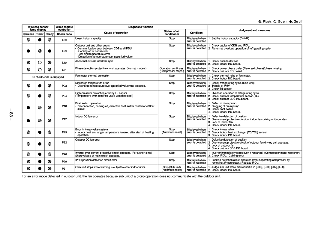
Error mode detected by indoor and outdoor units
10-2. Check Code List
Page
Error mode detected by central remote controller
Error mode detected by remote controller
Type B
10-3. Error Mode Detected by LED on Outdoor P.C. Board
Type A
10-4-1. Check Code
10-4. Troubleshooting Procedure for Each Check Code
Are 1, 2, 3 inter-unit cables normal?
E04 error
Are connections from connectors
Revised Mar
L09 error
E10 error
E18 error
E08, L03, L07, L08 error
F10 error
L20 error
L30 error
P10 error
CN334
P12 error Only for 4-way air discharge cassette type models
Revised Mar
CN333
Revised Mar
P22 error
CN301, *CN303 CN300
Revised Mar
P19 error
F02 error
Is connection of TC sensor connector
Are not “P26” and “14” errors output
F01 error
P26 error
Is connection of TCJ sensor connector
For RAV-SM563AT-E
P29 error
H03 error
Revised Mar
TE/TS sensor connectors of CDB CN604/CN605 normal?
F06 error
F04 error
F08 error
Revised Mar
L29 error
H02 error
IPDU P.C. board error Defect ÆReplace
Check parts. Defect ÆReplace
P03 error
H01 error
Revised Mar
protective operation by
P04 error
Revised Mar
Is high-voltage
Can handy remote controller control
C06 error Central controller
P31 error Sub indoor unit
E03 error Master indoor unit
F29 error / 12 error
Caracteristics-3
TA sensor
TC, TCJ sensor
30 Caracteristics-2 Caracteristics-1
Requirement when replacing the service indoor P.C. board assembly
11. REPLACEMENT OF SERVICE INDOOR P.C. BOARD
Minimum requirements for item code
r1 Readout of the setup data from EEPROM
r2 Replacement of service P.C. board
REMOTE CONTROLLER
r3 Writing of the setup contents to EEPROM
Revised Mar
Memorandum for setup contents Item code table Example
12-1. Indoor Unit
12. SETUP AT LOCAL SITE AND OTHERS
12-1-1. Test Run Setup on Remote Controller
Revised Mar
Except 4-way Air Discharge Cassette Type and Under Ceiling Type
Outline of test operation from the wireless remote controller
4, 5
At shipment
Revised Mar
Item No. DN table Selection of function
Description
Wireless remote controller Under Ceiling Type only
12-1-2. Cabling and Setting of Remote Controller Control
2-remote controller control Controlled by two remote controllers
How to set wired remote controller as sub remote controller
12-1-3. Monitor Function of Remote Controller Switch
Item code 01 Latest → Item code 04 Old
1 2
12-2-1. TCC-LINK Adapter For TCC-LINK Central Control
12-2. Setup at Local Site / Others
Size
4. Wiring Specifications
5. P.C. Board Switch SW01 Setup
12-3. How to set up central control address number
13-1. Address Setup
13. ADDRESS SETUP
13-2-2. Automatic address example from unset address No miscabling
13-2. Address Setup & Group Control
13-2-1. System configuration
Only turning on source power supply Automatic completion
13-3. Address Setup
2, 5
3, 6, 9 4, 7
1 2 3 4 5 6 7 8 9 10 11 END
button, the unit numbers
1 2 END
1 2 3 END
ON / OFF button if the unit stops
14-1-1. 4-Way Air Discharge Cassette Type
14. DETACHMENTS
Procedure
Revised Mar
Remarks
Procedure
louver connector
No. Part name
Card-edge spacer
Procedure
No. Part name
Remarks
Remarks
Procedure
Screws fixing earth lead wires
No. Part name
No. Part name
Procedure
‡ Drain pan 1. Detachment
2. Attachment
No. Part name
Procedure
ˆ Drain pump 1. Detachment
3. Attachment
Remarks
Procedure
Part name
Remarks
Procedure
14-1-2. Concealed Duct Type
No. Part name
Remarks
Procedure
Float switch holder
No. Part name
6 -3. View from reverse side of drain pump
Procedure
No. Part name
Remarks
Remarks
Procedure
14-1-3. Under Ceiling Type
No. Part name
Remarks
Procedure
No. Part name
Fixing louver motor and louver drive member
Procedure
No. Part name
Remarks
Heat exchanger support
Procedure
Part name
Remarks
No. Part name
Procedure
Revised Mar
14-2. Outdoor Unit
Front cabinet
Procedure
Remarks
Part name
Remarks
Procedure
REQUIREMENT
No. Part name
„ Control P.C
Procedure
No. Part name
Remarks
… Rear cabinet
Procedure
Part name
Remarks
Compressor
Procedure
No. Part name
Remarks
2. Attachment
Procedure
2. Attachment
1. Detachment
Remarks
Procedure
Revised Mar
No. Part name
Discharge port
Procedure
No. Part name
Remarks
Part name
Procedure
Inverter assembly
REQUIREMENT
Remarks
Procedure
Part name
Remarks
Procedure
No. Part name
Remarks
Procedure
wires 3 positions
Part name
support
Procedure
No. Part name
Remarks
Part name
Procedure
Detachment
Attachment
Perform work on a corrugated card
Procedure
No. Part name
Remarks
No. Part name
Procedure
REQUIREMENT
REQUIREMENT
Part name
Procedure
Detachment
2. Attachment
Part name
Procedure
Inverter assembly
Inverter assembly
Remarks
Procedure
Cycle control P.C. board assembly
Part name
Remarks
Procedure
Part name
Cautions in assembling fan motor
Procedure
Part name
Remarks
Part name
Procedure
1. Detachment
2. Attachment
No. Part name
Procedure
REQUIREMENT
REQUIREMENT
Remarks
Procedure
Cautions for assembling
Part name
15-1-1. 4-Way Air Discharge Cassette Type
15. EXPLODED VIEWS AND PARTS LIST
Revised Mar
15-1. Indoor Unit
43160565
402 404 401 405 403
Part
Description
224 212 205 231
Description
402 404 401 405 403
Part
216, 218
Revised Mar
224
211 225 209 202 226
Description
402 404 401 405 403
Part
Description
304 311 306 305 301 307
303 310 313 308
Part
15-1-2. Concealed Duct Type
3, 902
4, 6
9, 10
Description
3, 904
901, 902, 903
Part
Part
3, 904
6, 7
901, 902
Description
402 404 403 406 405401407
\Location
Part
22, 23
SETTING
44, 45
1, 2
Description
Part
Description
Part
Part
404401 407
Part
Description
13, 15
Revised Mar
21, 22
14, 16, 17
Part
705 701 702 708 707 706
Part
Description
Part
Revised Mar
3332
15, 16
Part
707 708 706 704 703 701 705
Part
Description
Description
21,22
16,17
Part
INVERTER COVER 708
28,29
Inverter
26,27
23,24
Description
702 TD SENSOR 701 TC SENSOR F6
703 SENSOR ASS’Y
Part
No. Part name
15-3. Replacement of Main Parts Sold Separately
Procedure
15-3-1. Drain up Kit
No. Part name
15-3-2. Wireless Remote Control Kit
Procedure
RBC-AX22CE2
Revised Mar
16. CORD HEATER INSTALLATION WORK
16-1. Required parts for installation work Recommendation
NOTE The parts on the above table are recommended parts
2. Required tools for installation work
3. Cord heater installation wiring diagram
Wiring cover
4. Cord heater installation work procedure
Photo / Explanatory diagram
Procedure
insulation board
Photo / Explanatory diagram
Procedure
Sound
Cord heater installation work
Photo / Explanatory diagram
Procedure
Rework the side cabinet L to remove part of it
Photo / Explanatory diagram
Procedure
Using screws Self-tapping screw type-B Ø4 × 8mm
Photo / Explanatory diagram
Procedure
Assembly
Upward
5. Drawing of thermostat fixing plate
Material SGCC-Z08, Thickness 0.8t
2-Ø3.4 burring hole
16-2. Base Plate 1. RAV-SM563AT-E, RAV-SM803AT-E
Revised Mar
Knockout
2. RAV-SM1103AT-E, RAV-SM1403AT-E
RAV-SP562AT-E, RAV-SP802AT-E, RAV-SP1102AT-E, RAV-SP1402AT-E
Check of Concentration Limit
WARNINGS ON REFRIGERANT LEAKAGE
2 CHOME 12-32, KONAN, MINATOKU, TOKYO, 108-0075, JAPAN
TOSHIBA CARRIER CORPORATION