3Com WX3000 Series Unified Switches Switching Engine
Manual Version 6W100
Environmental Statement
Part Contents
About This Manual
Organization
Conventions
Convention Description Boldface
Italic
Related Documentation
Convention Description
Create Folder
Manual Description
Obtaining Documentation
Table of Contents
CLI Configuration
Command Hierarchy
Introduction to the CLI
Switching User Levels
Setting a user level switching password
Switching to a specific user level
Setting the Level of a Command in a Specific View
Configuration example
Setting the level of a command in a specific view
CLI Views
Display Execute Operation
Quit
Quit or return
Gigabitethernet command
Vlan-interface command
Region-configuration
Peer-public-key command
Public-key-c
Ode end
Public-key-code begin
Execute the radius scheme
CLI Features
Vlan-vpn enable
Execute Command should be first
Online Help
Command History
Terminal Display
Partial online help
Press Ctrl+C
Error Prompts
Command Edit
Press… To…
Tab
Table of Contents
Page
Logging In to the Switching Engine
Logging In to the Switching Engine
Introduction to the User Interface
Supported User Interfaces
Common User Interface Configuration
User Interface Index
Display users all
Display user-interface
Type number number
Display web users
Logging In to the Switching Engine Through OAP
Press Enter to enter user view of the switching engine
Logging In Through OAP
OAP Overview
Configure the management IP
Not configured by default
Oap management-ip
Address of an OAP module
Resetting the OAP Software System
Reset the OAP software
Oap reboot slot
Common Configuration
Configuration Description
Logging In Through Telnet
Introduction
Telnet Configurations for Different Authentication Modes
Authentication Telnet configuration Description Mode
Telnet Configuration with Authentication Mode Being None
Configuration Procedure
Configuration Example
Configuration procedure
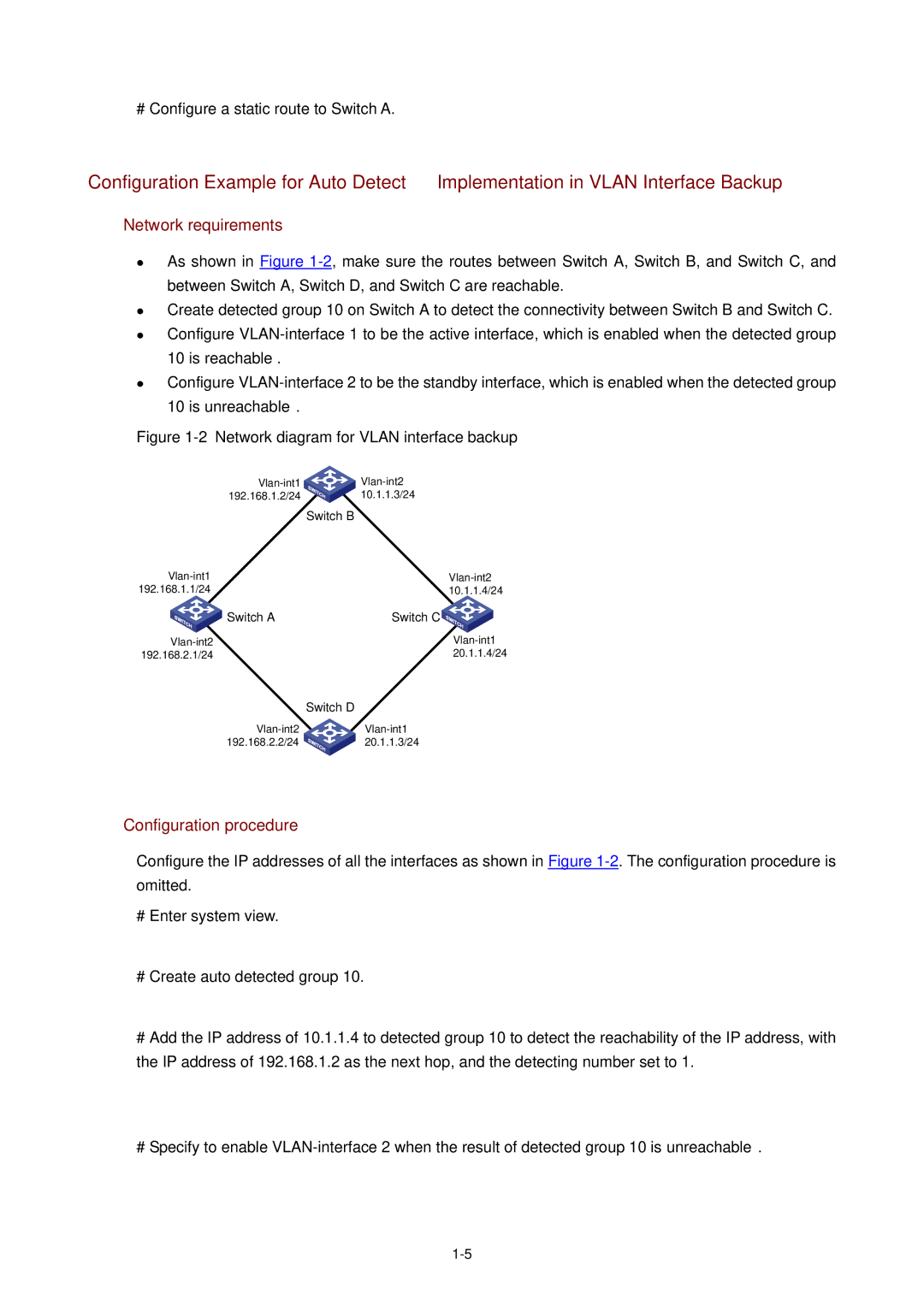
Network requirements
Password Set authentication
Password cipher
Auto-execute command
User privilege level level
Set the history command buffer
Default history command
Command buffer can store up to
Commands by default
Telnet Configuration with Authentication Mode Being Scheme
Scheme command
Authorization
History-command max-size
Protocol inbound all ssh
Service-type
User privilege level level command is Level level
Privilege
# Create a local user named guest and enter local user view
Telnetting to the Switching Engine
Telnetting to the Switching Engine from a Terminal
Deviceoap connect slot Connected to OAP
Page
Device telnet
Vlan interface of the switching engine is assigned an IP
User name and password for logging in to the Web-based
Network management system are configured
Logging In from the Web-Based Network Management System
Setting Up a Web Configuration Environment
Configuring the Login Banner
3The login page of the Web-based network management system
Header login text
By default, no login banner is
Through Web Configured
Follow these steps to enable/disable the WEB server
Enable the Web server
Enabling/Disabling the WEB Server
Ip http shutdown
Connection Establishment Using NMS
Logging In from NMS
Related information
Configuring Source IP Address for Telnet Service Packets
Configuring Source IP Address for Telnet Service Packets
Configuration in user view
Configuration in system view
Displaying Source IP Address Configuration
Interface-number
Login mode Control method Implementation Reference
User Control
Controlling Telnet Users
Prerequisites
Match-order config auto
Acl number acl-number
Rule rule-id deny permit
Acl acl-number inbound
Controlling Telnet Users by Source MAC Addresses
Rule rule-id deny
Permit rule-string
Controlling Network Management Users by Source IP Addresses
Controlling Network Management Users by Source IP Addresses
2Network diagram for controlling Snmp users using ACLs
Controlling Web Users by Source IP Address
Disconnecting a Web User by Force
Controlling Web Users by Source IP Addresses
Ip http acl acl-number
Free web-users all user-id
Device ip http acl
Table of Contents
Configuration File Management
Introduction to Configuration File
Types of configuration
Format of configuration file
Management of Configuration File
Saving the Current Configuration
Startup with the configuration file
Modes in saving the configuration
Erasing the Startup Configuration File
Three attributes of the configuration file
Specifying a Configuration File for Next Startup
Assign main attribute to the startup configuration file
Assign backup attribute to the startup configuration file
Startup saved-configuration
Displaying and Maintaining Device Configuration
Table of Contents
Vlan Overview
Vlan Overview
Introduction to Vlan
Advantages of VLANs
How Vlan Works
Vlan tag
MAC address learning mechanism of VLANs
2Encapsulation format of traditional Ethernet frames
Port-Based Vlan
Vlan Interface
Vlan Classification
Protocol-Based Vlan
Introduction to Protocol-Based Vlan
Encapsulation Format of Ethernet Data
Ethernet II and 802.2/802.3 encapsulation
Extended encapsulation formats of 802.2/802.3 packets
6802.3 raw encapsulation format
Procedure for the Switch to Judge Packet Protocol
Encapsulation Formats
Implementation of Protocol-Based Vlan
Encapsulation Ethernet 802.3 raw 802.2 LLC Snap Protocol
Page
Vlan Configuration
Vlan Configuration
Configuration Task List
Basic Vlan Configuration
Basic Vlan Interface Configuration
Configuration prerequisites
Displaying and Maintaining Vlan
Configuring a Port-Based Vlan
Configuring a Port-Based Vlan
Protocol-Based Vlan Configuration Example
Port interface-list
# Configure GigabitEthernet 1/0/10 of Switch B
# Create Vlan 201, and add GigabitEthernet 1/0/2 to Vlan
# Create Vlan 201, and add GigabitEthernet 1/0/12 to Vlan
Configuring a Protocol-Based Vlan
Configuring a Protocol Template for a Protocol-Based Vlan
Associating a Port with a Protocol-Based Vlan
Interface interface-type Interface-number
Port hybrid protocol-vlan
Vlan vlan-id protocol-index
Displaying and Maintaining Protocol-Based Vlan
Display vlan vlan-id to vlan-id all
Dynamic static
Display protocol-vlan vlan vlan id
Vlan
Protocol-Type
Table of Contents
Auto Detect Configuration
Introduction to the Auto Detect Function
Auto Detect Configuration
Auto Detect Basic Configuration
Auto Detect Implementation in Vlan Interface Backup
Auto Detect Implementation in Static Routing
Ip route-static ip-address mask
Preference-value reject blackhole
Auto Detect Configuration Examples
Vlan -id
Standby detect-group
# Configure a static route to Switch a
Is reachable
# Create auto detected group
Table of Contents
Voice Vlan Configuration
Voice Vlan Overview
How an IP Phone Works
1Network diagram for IP phones
Agent
Configuring Operation Mode for Voice Vlan
How the Device Identifies Voice Traffic
Number OUI address Vendor
Processing mode of tagged packets sent by IP voice devices
Support for Voice Vlan on Various Ports
Security Mode of Voice Vlan
Port type Supported or not Traffic type Mode
Port voice Voice
Voice Vlan Configuration
Configuration Prerequisites
Configuring a Voice Vlan to Operate in Automatic Mode
Configuring a Voice Vlan to Operate in Manual Mode
Enable
Undo voice vlan mode
Voice vlan security
Port trunk permit vlan
Port hybrid vlan vlan-id
Tagged untagged
Port trunk pvid vlan
Voice Vlan Configuration Example
Voice Vlan Configuration Example Automatic Mode
Displaying and Maintaining Voice Vlan
Voice Vlan Configuration Example Manual Mode
# Enable the voice Vlan function globally
# Configure GigabitEthernet 1/0/1 as a hybrid port
# Enable the voice Vlan function on GigabitEthernet 1/0/1
# Create Vlan 2 and configure it as a voice Vlan
# Configure GigabitEthernet 1/0/1 to operate in manual mode
Verification
# Display the status of the current voice Vlan
Table of Contents
Gvrp Configuration
Garp messages and timers
Introduction to Gvrp
Operating mechanism of Garp
Garp message format
Garp packets are in the following format
1Format of Garp packets
Field Description Value
Gvrp Configuration
Protocol Specifications
Configuration Prerequisite
Enabling Gvrp
Configuring Gvrp Timers
Garp timer leaveall
Garp timer hold join
Gvrp
Configuring Gvrp Port Registration Mode
Displaying and Maintaining Gvrp
Gvrp Configuration Example
Gvrp Configuration Example
Configure Switch a # Enable Gvrp globally
# Enable Gvrp on GigabitEthernet 1/0/1
# Enable Gvrp on GigabitEthernet 1/0/3
SwitchE-GigabitEthernet1/0/1 gvrp registration fixed
Table of Contents
Basic Port Configuration
Ethernet Port Overview
Types and Numbers of Ethernet Ports
Combo Ports Mapping Relations
Configuring the Default Vlan ID for an Ethernet Port
Link Types of Ethernet Ports
Configuring Ethernet Ports
Making Basic Port Configuration
Adding an Ethernet Port to Specified VLANs
Vlan tag
Configuring Port Auto-Negotiation Speed
Setting the Ethernet Port Broadcast Suppression Ratio
Enabling Flow Control on a Port
Speed auto 10 100
Broadcast-suppression
Configuring Access Port Attribute
Configuring Hybrid Port Attribute
Configuring Trunk Port Attribute
Configuration tasks
Disabling Up/Down Log Output on a Port
Copying Port Configuration to Other Ports
Configuring a Port Group
System-view Copy configuration source interface-type
Aggregation-group destination-agg-id
Setting Loopback Detection for an Ethernet Port
Configuring the Ethernet Port to Run Loopback Test
Configure the Ethernet port to run
Loopback-detection per-vlan
Loopback detection only on VLANs for the trunk and hybrid
Enabling the System to Test Connected Cable
Virtual-cable-test
Flow-interval interval
Ethernet Port Configuration Example
Displaying and Maintaining Ethernet Ports
Troubleshooting Ethernet Port Configuration
# Configure the default Vlan ID of GigabitEthernet 1/0/1 as
Table of Contents
Link Aggregation Configuration
Introduction to Link Aggregation
Introduction to Lacp
Operation Key
Manual Aggregation Group
Introduction to manual aggregation group
Port status in manual aggregation group
Static Lacp Aggregation Group
Introduction to static Lacp aggregation
Port status of static aggregation group
Configuring system priority
Dynamic Lacp Aggregation Group
Introduction to dynamic Lacp aggregation group
Port status of dynamic aggregation group
Configuring port priority
Aggregation Group Categories
Link Aggregation Configuration
Configuring a Manual Aggregation Group
Configuring a Static Lacp Aggregation Group
Description agg-name
Port link-aggregation group
Agg-id
Configuring a Dynamic Lacp Aggregation Group
Lacp system -priority
System-priority
Link Aggregation Configuration Example
Displaying and Maintaining Link Aggregation
Switch a Link aggregation Switch B
Page
Table of Contents
Port Isolation Configuration
Port Isolation Configuration
Port Isolation Overview
Introduction to Port Isolation
Port Isolation Configuration Example
Displaying and Maintaining Port Isolation
Device-GigabitEthernet1/0/4 quit device
Table of Contents
Port Security Configuration
Port Security Features
Port Security Overview
Introduction
Security mode Description Feature
This mode
Port Security Modes
Neither
Security mode Description Feature
Port Security Configuration
Complete the following tasks to configure port security
Follow these steps to enable port security
Enabling Port Security
Setting the Port Security Mode
Port-security oui OUI-value UserLoginWithOUI mode, a
Port-security max-mac-count
Count-value
Configuring Port Security Features
Configuring the NTK feature
Configuring intrusion protection
Configuring the Trap feature
Configuring Security MAC Addresses
Displaying and Maintaining Port Security Configuration
Port Security Configuration Example
HostSwitch
# Enable port security
# Set the port security mode to autolearn
# Enter GigabitEthernet 1/0/1 port view
Port Binding Configuration
Displaying and Maintaining Port Binding Configuration
Configuring Port Binding
Port Binding Overview
Port Binding Configuration Example
Configure switch a as follows # Enter system view
Table of Contents
Dldp Configuration
Dldp Overview
Dldp Fundamentals
Dldp status
Status Description
Dldp timers
Dldp works with the following timers 2DLDP timers
Timer Description
Interval of sending advertisement packets, which can be
Dldp operating mode
Enhanced timer then sends one probe packets every one
Mode During neighbor
Entry aging Timer expire
Packet type Processing procedure
No Echo packet received from Processing procedure Neighbor
4Types of packets sent by Dldp
Dldp status Packet types
Dldp Configuration
Precautions During Dldp Configuration
Dldp Configuration Tasks
Dldp neighbor state
Resetting Dldp Status
Reset the Dldp status of a port Dldp reset
This command only applies to the ports in Dldp down status
Dldp Network Example
# Enable Dldp globally
# Configure Dldp to work in enhanced mode
# Set the interval of sending Dldp packets to 15 seconds
# Display the Dldp status
Table of Contents
MAC Address Table Management
Introduction to MAC Address Table
Introduction to MAC Address Learning
1MAC address learning diagram
Managing MAC Address Table
Aging of MAC address table
Configuring MAC Address Table Management
Entries in a MAC address table
Configuring a MAC Address Entry
Adding a MAC address entry in system view
Adding a MAC address entry in Ethernet port view
System-view Mac-address static dynamic
Setting the Aging Time of MAC Address Entries
Mac-address timer aging
Age no-aging
Disabling MAC Address learning for a Vlan
Mac-address
Max-mac-count count
Max-mac-count
Configuration Example
Displaying and Maintaining MAC Address Table
Adding a Static MAC Address Entry Manually
Display mac-address
Table of Contents
Page
Mstp Configuration
STP Overview
STP Overview
Classification Designated bridge Designated port
All the ports on the root bridge are designated ports
How STP works
Step Description
Step Description
Device Port name Bpdu of port
5Comparison process and result on each device
Device Comparison process Bpdu of port after
Device Comparison process Bpdu of port after
3The final calculated spanning tree
Features of Mstp
Mstp Overview
Background of Mstp
Disadvantages of STP and Rstp
Basic Mstp Terminologies
MST region
Vlan mapping table
Region root
Common root bridge
Port role
Port state
MSTP, a port can be in one of the following three states
Principle of Mstp
Calculate the Cist
Calculate an Msti
Implement STP algorithm
Mstp Implementation on the Device
Configuring Root Bridge
Complete the following tasks to configure a root bridge
STP-related Standards
Bpdu guard Loop guard TC-BPDU attack guard Bpdu packet drop
Configuring an MST Region
# Verify the above configuration
Centi-seconds
Stp instance instance-id root secondary
Configuring the Bridge Priority of the Current Device
Required Default bridge priority of a Current device
Set the bridge priority for
Stp instance instance-id
Stp interface interface-type
Interface-number compliance
Auto dot1s legacy
Configuring the Mstp Operation Mode
Stp mode stp rstp mstp
Stp compliance auto dot1s
Legacy
Configuring the Maximum Hop Count of an MST Region
Configuring the Network Diameter of the Switched Network
Stp max-hops hops
Configuring the Mstp Time-related Parameters
Stp timer forward-delay
Stp timer hello
Stp timer max-age
Configuring the Timeout Time Factor
Stp interface interface-list
Transmit-limit packetnum
Stp transmit-limit packetnum
Configuring the Current Port as an Edge Port
Configure a port as an edge port in system view
Configure a port as an edge port in Ethernet port view
Edged-port enable
Point-to-point force-true
Force-false auto
Stp enable
Disable
Enabling Mstp
Stp point-to-point force-true
Configuring Leaf Nodes
Stp disable
Task Remarks
Configuring the MST Region
Configuring a Port as an Edge Port
Configuring the Path Cost for a Port
Standards for calculating path costs of ports
Stp pathcost-standard
Dot1d-1998 dot1t legacy
Configure the path cost for specific ports
Configuration example a
Configuration example B
Configuring Port Priority
Configure port priority in system view
Configure port priority in Ethernet port view
Instance instance-id port
Performing mCheck Operation
Perform the mCheck operation in system view
Perform the mCheck operation in Ethernet port view
Stp interface interface-list mcheck
Configuring Guard Functions
Bpdu guard
Root guard
Stp mcheck
Loop guard
TC-BPDU attack guard
Bpdu dropping
Configuring Bpdu Guard
Configuring Root Guard
Root-protection
Stp root-protection
Configuring Loop Guard
Configuring TC-BPDU Attack Guard
Stp loop-protection
Stp tc-protection
Configuring Digest Snooping
Configuring Bpdu Dropping
Interface interface-name
Bpdu-drop any
Configuring Digest Snooping
Stp config-digest-snooping
Configuring Rapid Transition
6The Rstp rapid transition mechanism
Configuring Rapid Transition
No-agreement-check
Stp no-agreement-check
Configuring VLAN-VPN Tunnel
Configuring VLAN-VPN tunnel
Vlan-vpn tunnel
STP Maintenance Configuration
Enabling Log/Trap Output for Ports of Mstp Instance
Stp instance instance id
Portlog
Enabling Trap Messages Conforming to 802.1d Standard
Displaying and Maintaining Mstp
Mstp Configuration Example
Configure Switch a # Enter MST region view
# Activate the settings of the MST region manually
Configure Switch B # Enter MST region view
Configure Switch C # Enter MST region view
# Configure the MST region
Configure Switch D # Enter MST region view
VLAN-VPN tunnel Configuration Example
Configure Switch a # Enable Mstp
Configure Switch B # Enable Mstp
Configure Switch C # Enable Mstp
# Enable the VLAN-VPN tunnel function
# Configure GigabitEthernet 1/0/2 as a trunk port
Configure Switch D # Enable Mstp
# Configure GigabitEthernet 1/0/1 as a trunk port
Table of Contents
802.1x Configuration
Architecture of 802.1x Authentication
Introduction to
Port access entity
Port access control method
Controlled port and uncontrolled port
Valid direction of a controlled port
Mechanism of an 802.1x Authentication System
Encapsulation of EAPoL Messages
Format of an EAPoL packet
Format of an EAP packet
802.1x Authentication Procedure
Fields added for EAP authentication
EAP relay mode
Describes the basic EAP-MD5 authentication procedure
EAP terminating mode
Timers Used
9802.1x authentication procedure in EAP terminating mode
Additional 802.1x Features Implemented
Checking the supplicant system
Checking the client version
Guest Vlan function
Introduction to 802.1x Configuration
Enabling 802.1x re-authentication
Basic 802.1x Configuration
Configuring Basic 802.1x Functions
Dot1x
Dot1x authentication-method chap
Dot1x handshake enable
Dot1x interface interface-list
Dot1x port-control authorized-force
Timer and Maximum User Number Configuration
Dot1x max-user user-number
Dot1x retry max-retry-value
Advanced 802.1x Configuration
Configuring Proxy Checking
Configuring Client Version Checking
Enabling DHCP-triggered Authentication
Configuring Guest Vlan
Dot1x dhcp-launch
Dot1x port-method portbased
Configuring 802.1x Re-Authentication
Configuring the 802.1x Re-Authentication Timer
Dot1x re-authenticate
802.1x Configuration Example
Displaying and Maintaining
# Enable 802.1x globally
# Enable 802.1x on GigabitEthernet 1/0/1 port
# Set the default user domain to be aabbcc.net
# Create a local access user account
# Create the domain named aabbcc.net and enter its view
Quick EAD Deployment Configuration
Configuring Quick EAD Deployment
Introduction to Quick EAD Deployment
Quick EAD Deployment Overview
Configuring a free IP range
Setting the ACL timeout period
Dot1x url url-string
Dot1x free-ip ip-address
Quick EAD Deployment Configuration Example
Displaying and Maintaining Quick EAD Deployment
Period is 30 minutes
Troubleshooting
Solution
System-Guard Configuration
Configuring the System-Guard Feature
Configuring the System-Guard Feature
System-Guard Overview
Displaying and Maintaining System-Guard
Table of Contents
Page
Authentication
Authorization
AAA Overview
Introduction to AAA
Introduction to AAA Services
What is Radius
Accounting
Introduction to ISP Domain
Basic message exchange procedure in Radius
1Databases in a Radius server
Radius message format
Code Message type Message description
Direction client-server
Client transmits this message to the server to determine if
Type field value Attribute type
What is Hwtacacs
Introduction to Hwtacacs
Basic message exchange procedure in Hwtacacs
5Network diagram for a typical Hwtacacs application
6AAA implementation procedure for a telnet user
Page
AAA Configuration
AAA Configuration Task List
Configuration Introduction
Creating an ISP Domain and Configuring Its Attributes
Configuring an AAA Scheme for an ISP Domain
Configuring a combined AAA scheme
Messenger time enable limit
Self-service-url disable
Configuring separate AAA schemes
Domain isp-name
Radius-scheme-name local
Hwtacacs-scheme
Configuring Dynamic Vlan Assignment
Local local none Authorization none
Accounting none
Configuring the Attributes of a Local User
Domain isp-name
Vlan-assignment-mode
Integer string
Password-display-mode
Service-type ftp lan-access
Authorization vlan string
Access-limit
Radius Configuration Task List
Cutting Down User Connections Forcibly
Follow these steps to cut down user connections forcibly
Cut down user
Configuring
Servers
Configuring Radius Authentication/Authorization Servers
Radius client enable
Creating a Radius Scheme
Radius scheme
Configuring Radius Accounting Servers
Primary authentication
Secondary authentication
Ip-address port-number
Configuring Shared Keys for Radius Messages
Secondary accounting
Stop-accounting-buffer
Retry stop-accounting
Configuring the Type of Radius Servers to be Supported
Key authentication string
Key accounting string
Configuring the Status of Radius Servers
Server-type extended
Optional Servers to be supported
State primary authentication
Authentication block
Calling-station-id mode
Block active
Configuring the Local Radius Authentication Server Function
Local-server enable
Key password
Local-server nas-ip ip-address
Configuring Timers for Radius Servers
Enabling the User Re-Authentication at Restart Function
Hwtacacs Configuration Task List
Accounting-on enable send
Times interval interval
Configuring Tacacs Authentication Servers
Creating a Hwtacacs Scheme
Hwtacacs scheme
Configuring Tacacs Authorization Servers
Primary authorization
Secondary authorization
Ip-address port
Configuring Tacacs Accounting Servers
Configuring Shared Keys for Hwtacacs Messages
Follow these steps to configure Tacacs accounting servers
Function is enabled Number of transmission
Authentication string
Key accounting
Mega-byte
Data-flow-format packet
Configuring the Timers Regarding Tacacs Servers
Scheme exists Set the response timeout time
Optional By default, the response timeout Tacacs servers
Optional By default, the real-time Interval
Displaying and Maintaining AAA
Displaying and maintaining AAA information
Displaying and maintaining Radius protocol information
AAA Configuration Examples
Remote Radius Authentication of Telnet/SSH Users
Displaying and maintaining Hwtacacs protocol information
# Adopt AAA authentication for Telnet users
# Configure an ISP domain
# Configure a Radius scheme
# Associate the ISP domain with the Radius scheme
Local Authentication of FTP/Telnet Users
# Create and configure a local user named telnet
Hwtacacs Authentication and Authorization of Telnet Users
# Configure the domain name of the Hwtacacs scheme to hwtac
Troubleshooting AAA
Troubleshooting Radius Configuration
Troubleshooting Hwtacacs Configuration
Possible reasons and solutions
EAD Configuration
Introduction to EAD
Typical Network Application of EAD
EAD Configuration
EAD Configuration Example
Security-policy-server
Ip-address
# Configure the IP address of the security policy server
# Associate the domain with the Radius scheme
Table of Contents
MAC Authentication Configuration
MAC Authentication Overview
Performing MAC Authentication on a Radius Server
Performing MAC Authentication Locally
Configuring Basic MAC Authentication Functions
MAC Authentication Timers
Mac-authentication
Related Concepts
Mac-authentication interface
Mac-authentication Quit
Mac-authentication authmode
Uppercase fixedpassword password
MAC Address Authentication Enhanced Function Configuration
Configuring a Guest Vlan
Mac-authentication timer
Guest-vlan vlan-id
Guest-vlan-reauth interval
Configure the maximum number
MAC address authentication Number of MAC address
Max-auth-num user-number
Displaying and Maintaining MAC Authentication
MAC Authentication Configuration Example
Display mac-authentication
Reset mac-authentication statistics
# Add a local user Specify the username and password
Set the service type to lan-access
# Specify to perform local authentication
# Add an ISP domain named aabbcc.net
Table of Contents
IP Addressing Configuration
IP Addressing Overview
IP Address Classes
Net-id
Special Case IP Addresses
Subnetting and Masking
Class Address range Remarks
Configuring IP Addresses
Ip address ip-address mask
Mask-length sub
IP Address Configuration Examples
IP Address Configuration Example
Displaying and Maintaining IP Addressing
Network requirement
4Network diagram for IP address configuration
Page
IP Performance Configuration
Configuring IP Performance
IP Performance Overview
Disabling Sending of Icmp Error Packets
Displaying and Maintaining IP Performance Configuration
Table of Contents
Dhcp Overview
Introduction to Dhcp
Dhcp IP Address Assignment
IP Address Assignment Policy
Obtaining IP Addresses Dynamically
Dhcp Packet Format
Updating IP Address Lease
Protocols and Standards
Dhcp Relay Agent Configuration
Introduction to Dhcp Relay Agent
Usage of Dhcp Relay Agent
Dhcp Relay Agent Fundamentals
Padding content of Option
Dhcp Relay Agent Support for Option
Introduction to Option
2Padding contents for sub-option 1 of Option
Mechanism of Option 82 supported on Dhcp relay agent
Configuring the Dhcp Relay Agent
Dhcp Relay Agent Configuration Task List
Dhcp-server groupNo ip
Ip-address &1-8
Configuring Dhcp Relay Agent Security Functions
Configuring address checking
Address-check enable
Dhcp relay hand enable
Dhcp-security static ip-address
Mac-address
Configuring the Dhcp Relay Agent to Support Option
Configuring the Dhcp relay agent to support Option
Enabling unauthorized Dhcp server detection
Prerequisites
Displaying and Maintaining Dhcp Relay Agent Configuration
Dhcp Relay Agent Configuration Example
Troubleshooting Dhcp Relay Agent Configuration
Symptom
Solution
Analysis
Page
Dhcp Snooping Configuration
Dhcp Snooping Overview
Function of Dhcp Snooping
Padding content and frame format of Option
Overview of Dhcp Snooping Option
Mechanism of DHCP-snooping Option
2Extended format of the circuit ID sub-option
Dhcp-snooping information format command or
Sub-option configuration Dhcp snooping device will…
Dhcp-snooping information format command or the default HEX
Overview of IP Filtering
Dhcp Snooping Configuration
Configuring Dhcp Snooping
DHCP-snooping table
IP static binding table
Configuring Dhcp Snooping to Support Option
DHCP-Snooping Option 82 Support Configuration Task List
Enable DHCP-snooping Option 82 support
Required Specify the current port as a
Configure a handling policy for Dhcp packets with Option
Configure the storage format of Option
Dhcp-snooping information
Strategy drop keep replace
Configure the circuit ID sub-option
Configure the remote ID sub-option
Vlan vlan-id circuit-id string
String
Configuring IP Filtering
Configure the padding format for Option
Remote-id sysname string
Vlan vlan-id remote-id
Dhcp Snooping Configuration Example
DHCP-Snooping Option 82 Support Configuration Example
IP Filtering Configuration Example
# Enable Dhcp snooping on Switch
# Enable DHCP-snooping Option 82 support
# Specify GigabitEthernet 1/0/5 as the trusted port
7Network diagram for IP filtering configuration
# Specify GigabitEthernet 1/0/1 as the trusted port
Displaying and Maintaining Dhcp Snooping Configuration
Display dhcp-snooping
Trust
Display ip source static
DHCP/BOOTP Client Configuration
Introduction to Bootp Client
Configuring a DHCP/BOOTP Client
Follow these steps to configure a DHCP/BOOTP client
Dhcp Client Configuration Example
Ip address bootp-alloc
Dhcp-alloc
Displaying and Maintaining DHCP/BOOTP Client Configuration
Display bootp client interface
Bootp client
Display related information on a
Table of Contents
ACL Configuration
ACL Overview
ACL Matching Order
Ways to Apply an ACL on a Device
Depth-first match order for rules of a basic ACL
Depth-first match order for rules of an advanced ACL
Being applied to the hardware directly
ACL Configuration
Configuring Time Range
Types of ACLs Supported by Devices
Time-range time-name start-time to end-time
Days-of-the-week from start-time start-date to
End-time end-date from start-time start-date to
End-time end-date to end-time end-date
Configuring Basic ACL
Auto config
Rule-string Rule-string , refer to ACL Command
Configuring Advanced ACL
Match-order auto config
Rule-string , refer to ACL Command
Rule rule-id permit deny
Configuring Layer 2 ACL
Rule-string Refer to ACL Command
ACL Assignment
Configure procedure
Assigning an ACL Globally
Assigning an ACL to a Vlan
Packet-filter inbound acl-rule
Assigning an ACL to a Port Group
System-view Packet-filter vlan vlan-id
Inbound acl-rule
Displaying and Maintaining ACL
Assigning an ACL to a Port
Example for Controlling Telnet Login Users by Source IP
Example for Controlling Web Login Users by Source IP
SwitchPC
Examples for Upper-layer Software Referencing ACLs
Basic ACL Configuration Example
Advanced ACL Configuration Example
Examples for Applying ACLs to Hardware
Layer 2 ACL Configuration Example
# Apply ACL 3000 on GigabitEthernet 1/0/1
Example for Applying an ACL to a Vlan
# Apply ACL 4000 on GigabitEthernet 1/0/1
# Apply ACL 3000 to Vlan
Table of Contents
Page
QoS Configuration
Traditional Packet Forwarding Service
Introduction to QoS
New Applications and New Requirements
QoS Supported by Devices
Major Traffic Control Techniques
Traffic Classification
Precedence
IP precedence, ToS precedence, and Dscp precedence
IP Precedence decimal IP Precedence binary Description
802.1p priority
Dscp value decimal Dscp value binary Description
Priority Trust Mode
802.1p priority decimal 802.1p priority binary Description
Trusting the 802.1p precedence
Trusting the Dscp precedence
Dscp precedence Target Dscp precedence
Protocol Priority
Priority Marking
Traffic Policing and Traffic Shaping
Token bucket
Evaluating the traffic with the token bucket
Traffic policing
Traffic shaping
Traffic Redirecting
Vlan Mapping
Queue Scheduling
7Diagram for SP queuing
SP queuing
Sdwrr
QoS Configuration
QoS Configuration Task List
Flow-based Traffic Accounting
Burst
Configuring Priority Trust Mode
Priority priority-level
Priority-trust cos automap
Priority-trust dscp automap
Configuring Priority Mapping
Qos cos-local-precedence-map
Qos cos-drop-precedence-map
Qos cos-dscp-map cos0-map-dscp
Qos dscp-local-precedence-map dscp-list
Qos dscp-drop-precedence-map dscp-list
Qos dscp-cos-map dscp-list cos-value
Page
Setting the Priority of Protocol Packets
System-view Protocol-priority
Protocol-type
Ip-precedence
Marking Packet Priority
Traffic-priority inbound acl-rule dscp
Dscp-value cos cos-value
Traffic-priority vlan vlan-id inbound acl-rule
Configuring Traffic Policing
Required Matching specific ACL rules
Reset traffic-limit inbound acl-rule
Reset traffic-limit vlan vlan-id inbound
Traffic-limit inbound acl-rule target-rate
Conform con-action exceed
Configuring Traffic Shaping
View Configure traffic
By default, traffic policing is Policing
Disabled Clear the traffic
Configuring Traffic Redirecting
Configuration examples
Traffic-shape queue
Traffic-redirect inbound acl-rule interface
Traffic-redirect vlan vlan-id inbound acl-rule
Configuring Vlan Mapping
Configuring Queue Scheduling
Traffic-remark-vlanid inbound
Acl-rule remark-vlan vlan-id
Queue-id queue-weight &1-8
Group2 queue-id queue-weight
Undo queue-scheduler queue-id
Queue-scheduler wrr group1
Reset traffic-statistic inbound
Collecting/Clearing Traffic Statistics
Collect the statistics on Packets matching specific ACL
Traffic-statistic inbound acl-rule
Reset traffic-statistic vlan vlan-id
Reset traffic-statistic inbound acl-rule
Traffic-statistic vlan vlan-id
Configuring Traffic Mirroring
Follow these steps to enable the burst function
Enabling the Burst Function
Refer to Burst for information about the burst function
Monitor-port
Mirrored-to inbound acl-rule
Monitor-interface
Mirrored-to vlan vlan-id
Traffic mirroring configuration
Required Destination port Exit current view
Required Mirroring for packets that
Displaying and Maintaining QoS
QoS Configuration Example
Configuration Example of Traffic Policing
Page
QoS Profile Configuration
QoS Profile Application Mode
Dynamic application mode
Manual application mode
QoS Profile Configuration
QoS Profile Configuration Task List
Configuring a QoS Profile
Applying a QoS Profile
Displaying and Maintaining QoS Profile
Qos-profile port-based
Undo qos-profile port-based
System-view Apply qos-profile
QoS Profile Configuration Example
1Network diagram for QoS profile configuration
# Enable
Table of Contents
Mirroring Configuration
Mirroring Overview
Local Port Mirroring
Remote Port Mirroring
Switch Ports involved Function
MAC-Based Mirroring
VLAN-Based Mirroring
1Ports involved in the mirroring operation
Mirroring Configuration
Configuring Local Port Mirroring
Configuring Remote Port Mirroring
Configuration on the device acting as a source switch
Configuration on the device acting as a destination switch
Configuring MAC-Based Mirroring
Remote-probe-vlan-id
Remote-destination
Monitor-port monitor-port
Configuring VLAN-Based Mirroring
Local remote-source
Mirroring-group group-id Mirroring-mac mac vlan
Mirroring Configuration Example
Local Port Mirroring Configuration Example
Displaying and Maintaining Port Mirroring
Mirroring-group group-id Mirroring-vlan vlan-id
Remote Port Mirroring Configuration Example
Configure Switch C # Create a local mirroring group
4Network diagram for remote port mirroring
# Configure Vlan 10 as the remote-probe Vlan
# Configure Vlan 10 as the remote-probe Vlan
Page
Table of Contents
ARP Configuration
Introduction to ARP
ARP Function
ARP Message Format
Field Description
Value Description
Experimental Ethernet
Proteon ProNET Token Ring
ARP entry Generation Method Maintenance Mode
ARP Table
ARP Process
Chaos
Introduction to ARP Attack Detection
Man-in-the-middle attack
ARP attack detection
Configuring ARP
Configuring ARP Basic Functions
Arp timer aging aging-time
Introduction to Gratuitous ARP
Configuring ARP Attack Detection
Arp check enable
Arp detection enable
Arp detection trust
Configuring Gratuitous ARP
Arp restricted-forwarding
Gratuitous-arp-learning
ARP Configuration Example
ARP Basic Configuration Example
ARP Attack Detection Configuration Example
Displaying and Maintaining ARP
# Enable Dhcp snooping on Switch a
# Enable ARP attack detection on all ports in Vlan
Table of Contents
Snmp Configuration
Snmp Overview
Snmp Operation Mechanism
Snmp Versions
MIB attribute MIB content Related RFC
Supported MIBs
MIB II based on TCP/IP network device RFC
Public MIB
Configuring Basic Snmp Functions
Configuring basic Snmp functions for SNMPv1 or SNMPv2c
Snmp-agent
Snmp-agent sys-info
Configuring basic Snmp functions for SNMPv3
Configuring Trap Parameters
Configuring Basic Trap
Configuring Extended Trap
Snmp Configuration Examples
Snmp Configuration Examples
Enabling Logging for Network Management
Displaying and Maintaining Snmp
Network procedure
2Network diagram for Snmp configuration
Configuring the NMS
Rmon Configuration
Introduction to Rmon
Working Mechanism of Rmon
Commonly Used Rmon Groups
Rmon Configuration
Rmon Configuration Examples
Configuration procedures
Displaying and Maintaining Rmon
# Display the Rmon extended alarm entry numbered
Table of Contents
Information Transmission in the Unicast Mode
Multicast Overview
Multicast Overview
Information Transmission in the Broadcast Mode
1Information transmission in the unicast mode
Information Transmission in the Multicast Mode
2Information transmission in the broadcast mode
3Information transmission in the multicast mode
Roles in Multicast
Multicast Models
Advantages and Applications of Multicast
Advantages of multicast
Application of multicast
Multicast Architecture
ASM model
SFM model
SSM model
IP multicast address
Class D address range Description
Reserved multicast addresses IP addresses for permanent
Ethernet multicast MAC address
Multicast Protocols
Layer 3 multicast protocols
Layer 2 multicast protocols
5Positions of Layer 3 multicast protocols
Multicast Packet Forwarding Mechanism
Implementation of the RPF Mechanism
RPF Check
7RPF check process
Page
Igmp Snooping Configuration
Igmp Snooping Overview
Principle of Igmp Snooping
Basic Concepts in Igmp Snooping
Timer Description Message before Action after expiry Expiry
Work Mechanism of Igmp Snooping
When receiving a general query
When receiving a membership report
When receiving a leave message
Igmp Snooping Configuration
Igmp Snooping Configuration Task List
Complete the following tasks to configure Igmp Snooping
Configuring the Version of Igmp Snooping
Igmp-snooping enable
Enabling Igmp Snooping
Igmp-snooping version
Configuring Timers
Configuring Fast Leave Processing
Enabling fast leave processing in system view
Configuring a Multicast Group Filter
Enable fast leave processing
Required By default, the fast leave For specific VLANs
Enabling fast leave processing in Ethernet port view
Configuring a multicast group filter in system view
Configuring a multicast group filter in Ethernet port view
Igmp -snooping group -policy
Acl-number vlan vlan-list
Configuring Igmp Querier
Igmp-snooping group-limit limit
Vlan vlan list overflow-replace
Configuring Static Member Port for a Multicast Group
Suppressing Flooding of Unknown Multicast Traffic in a Vlan
Configuring a Static Router Port
Ethernet port view
Vlan interface view
Multicast static-group
Configuring a Port as a Simulated Group Member
Vlan view
Igmp host-join group-address
Source-ip source-address
Configuring a Vlan Tag for Query Messages
Configuring Multicast Vlan
Vlan-mapping vlan
Igmp enable
Service-type multicast
Hybrid Port hybrid vlan vlan-id-list
Port trunk permit vlan vlan-list
Igmp Snooping Configuration Examples
Configuring Igmp Snooping
Displaying and Maintaining Igmp Snooping
3Network diagram for Igmp Snooping configuration
Configure Switch a # Enable Igmp Snooping globally
Device Device description Networking description
Interface IP address of Vlan 20 is
GigabitEthernet 1/0/1 is connected to the workstation
4Network diagram for multicast Vlan configuration
# Configure Vlan
Troubleshooting Igmp Snooping
Symptom Multicast function does not work on the device
Common Multicast Configuration
Common Multicast Configuration
Configuring a Multicast MAC Address Entry
Mac-address multicast
Displaying and Maintaining Common Multicast Configuration
Configuring Dropping Unknown Multicast Packets
Unknown-multicast drop
Display mac-address multicast
Table of Contents
NTP Configuration
Introduction to NTP
Applications of NTP
Implementation Principle of NTP
NTP Implementation Modes
1Implementation principle of NTP
Server/client mode
Symmetric peer mode
Broadcast mode
Multicast mode
NTP implementation Configuration on the device Mode
NTP Configuration Task List
Configuring NTP Implementation Modes
Configuring NTP Server/Client Mode
Complete the following tasks to configure NTP
Configuring the NTP Symmetric Peer Mode
Configuring NTP Broadcast Mode
Configure the device to work
Ntp-service broadcast-server
NTP broadcast server
Configuring NTP Multicast Mode
Configuring the device to work in the multicast server mode
Configuring the device to work in the multicast client mode
Configuring Access Control Right
Configuring NTP Authentication
Ntp-service access peer
Server synchronization
Configuring NTP authentication on the client
Role of device Working mode
Configuring NTP authentication on the server
Configuring Optional NTP Parameters
Configure on NTP Broadcast Server
Mode and NTP multicast Broadcast
While Configuring
Displaying and Maintaining NTP Configuration
NTP Configuration Examples
Disabling an Interface from Receiving NTP messages
Max-dynamic-sessions
# Set Device a as the NTP server of Device B
Configuring NTP Symmetric Peer Mode
Configure Device C # Set Device a as the NTP server
# Set Device C as the peer of Device B
8Network diagram for the NTP broadcast mode configuration
Configure Device C # Enter system view
# Set Device a as a broadcast client
9Network diagram for NTP multicast mode configuration
Configuring NTP Server/Client Mode with Authentication
Configure Device B # Enter system view
# Enable the NTP authentication function
# Specify the key 42 as a trusted key
Table of Contents
SSH Configuration
SSH Overview
Introduction to SSH
Algorithm and Key
Asymmetric Key Algorithm
SSH Operating Process
Stages Description
Authentication negotiation
Version negotiation
Key negotiation
Configuring the SSH Server
Session request
Data exchange
SSH Server Configuration Tasks
Configuring the Protocol Support for the User Interface
Authentication-mode scheme
Command-authorization
Generating/Destroying a RSA or DSA Key Pair
Creating an SSH User and Specify an Authentication Type
Exporting the RSA or DSA Public Key
Specifying a Service Type for an SSH User
Configuring SSH Management
Ssh user username service-type
Stelnet sftp all
Configuring the Client Public Key on the Server
Public-key-code end
Peer-public-key end
Rsa peer-public-key keyname
Assigning a Public Key to an SSH User
Specifying a Source IP Address/Interface for the SSH Server
Ssh user username assign
Publickey rsa-key keyname
Configuring the SSH Client
SSH Client Configuration Tasks
Configuring the SSH Client Using an SSH Client Software
Generate a client key
2Generate a client key
4Generate the client keys
Specify the IP address of the Server
Launch PuTTY.exe. The following window appears
Select a protocol for remote connection
Select an SSH version
As shown in -7, select SSH under Protocol
Open an SSH connection with publickey authentication
8SSH client configuration interface
10SSH client interface
Configuring the SSH Client on an SSH2-Capable Device
Open an SSH connection with password authentication
Configure whether first-time authentication is supported
Establish the connection between the SSH client and server
Displaying and Maintaining SSH Configuration
Specifying a Source IP address/Interface for the SSH client
Ssh2 source-ip ip-address
Ssh2 source-interface
SSH Configuration Examples
# Enable the user interfaces to support SSH
# Generate RSA and DSA key pairs
Page
14SSH client interface
# Set the client’s command privilege level to
# Assign the public key Switch001 to client client001
Page
18Generate a client key pair
Page
22SSH client interface
Device system-view Device interface vlan-interface
# Establish a connection to the server
# Set the user command privilege level to
# Assign the public key Switch001 to user client001
# Generate a DSA key pair
25Network diagram of SSH client configuration
# Set AAA authentication on user interfaces
# Configure the user interfaces to support SSH
# Assign public key Switch001 to user client001
# Specify the host public key pair name of the server
# Establish the SSH connection to server
Table of Contents
File System Management Configuration
File System Configuration
File System Configuration Tasks
Introduction to File System
File Operations
Prompt Mode Configuration
Flash Memory Operations
Execute filename
Format device
File System Configuration Example
File prompt alert quiet
File Attribute Configuration
Attribute Description Feature Identifier
Introduction to File Attributes
Configuring File Attributes
Table of Contents
FTP and Sftp Configuration
Introduction to FTP and Sftp
Introduction to FTP
Description Remarks
FTP Configuration
FTP Configuration The Device Operating as an FTP Server
Service-type ftp
Introduction to Sftp
Configuring connection idle time
Ftp timeout minutes
Enabling an FTP server
Disconnecting a specified user
Ftp-server source-interface
Ftp-server source-ip ip-address
Ftp disconnect user-name
Configuring the banner for an FTP server
FTP Configuration The Device Operating as an FTP Client
Basic configurations on an FTP client
Displaying FTP server information
Cdup
Lcd
Disconnect
Close
Configuration Example The Device Operating as an FTP Server
# Upload the config.cfg file. ftp put config.cfg
FTP Banner Display Configuration Example
4Network diagram for FTP banner display configuration
# Enter the authorized directory on the FTP server
Sftp Configuration
Sftp Configuration The Device Operating as an Sftp Server
Complete the following tasks to configure Sftp
Follow these steps to enable an Sftp server
Sftp Configuration The Device Operating as an Sftp Client
Basic configurations on an Sftp client
Ftp timeout time-out-value
Time for the Sftp server Minutes by default
Help all command-name
Sftp host-ip host-name
Delete remotefile
Remove remote-file
Sftp Configuration Example
Sftp source-interface
Sftp source-ip ip-address
Display sftp source-ip
# Specify the SSH authentication mode as AAA
# Specify the service type as Sftp
# Enable the Sftp server
# Create a local user client001
Sftp-client
# Exit Sftp
Tftp Configuration
Tftp Configuration
Complete the following tasks to configure Tftp
Introduction to Tftp
Tftp Configuration The Device Operating as a Tftp Client
Basic configurations on a Tftp client
Tftp ascii binary
Tftp-server acl acl-number
Tftp Configuration Example
Tftp source-interface
Tftp source-ip ip-address
Display tftp source-ip
Device tftp 1.1.1.2 get config.cfg config.cfg
Table of Contents
Information Center
Information Center Overview
Introduction to Information Center
Classification of system information
Ten channels and six output directions of system information
Outputting system information by source module
Module name Description
System Information Format
Priority
Timestamp
Sysname
Information Center Configuration
Introduction to the Information Center Configuration Tasks
Configuring Synchronous Information Output
Set for the system
Setting to Output System Information to the Console
Setting to output system information to the console
Enabling system information display on the console
Terminal monitor
Terminal debugging
Terminal logging
Setting to Output System Information to a Monitor Terminal
Setting to output system information to a monitor terminal
Enabling system information display on a monitor terminal
Info-center monitor channel
Setting to Output System Information to a Log Host
Info-center loghost
Info-center loghost source
Setting to Output System Information to the Trap Buffer
Setting to Output System Information to the Log Buffer
Info-center trapbuffer
Info-center source
Setting to Output System Information to the Snmp NMS
Info-center logbuffer
Info-center snmp channel
Information Center Configuration Examples
Displaying and Maintaining Information Center
Log Output to a Unix Log Host
# mkdir /var/log/Switch # touch /var/log/Switch/information
2Network diagram for log output to a Linux log host
Log Output to a Linux Log Host
3Network diagram for log output to the console
Log Output to the Console
# Enable terminal display
4Network diagram
Table of Contents
Host Configuration File Loading
Remote Loading Using FTP
Loading procedure using FTP client
Introduction to Loading Approaches
Loading procedure using FTP server
Restart Switch
2Remote loading using FTP server
Use the put command to upload the file config.cfg to Switch
Remote Loading Using Tftp
Basic System Configuration and Debugging
Basic System Configuration
Displaying the System Status
Debugging the System
Enabling/Disabling System Debugging
Display clock
Displaying Debugging Status
Displaying Operating Information about Modules in System
Network Connectivity Test
Network Connectivity Test
Ping
Tracert
Device Management Configuration
Device Management Configuration Tasks
Rebooting the Device
Device Management
Scheduling a Reboot on the Device
Schedule reboot at hhmm
Schedule reboot delay
Schedule reboot regularity
Identifying and Diagnosing Pluggable Transceivers
Introduction to pluggable transceivers
Identifying pluggable transceivers
Diagnosing pluggable transceivers
Table of Contents
VLAN-VPN Configuration
VLAN-VPN Overview
Introduction to VLAN-VPN
Adjusting the Tpid Values of VLAN-VPN Packets
Implementation of VLAN-VPN
VLAN-VPN Configuration
Enabling the VLAN-VPN Feature for a Port
Protocol type Value
Tpid Adjusting Configuration
Vlan-vpn uplink enable
Displaying and Maintaining VLAN-VPN
Vlan-vpn tpid value
VLAN-VPN Configuration Example
4Network diagram for VLAN-VPN configuration
SwitchA vlan-vpn tpid
Data transfer process
Page
Selective QinQ Configuration
Selective QinQ Overview
Selective QinQ Overview
Selective QinQ Configuration
Enabling the Selective QinQ Feature for a Port
Inner-to-Outer Tag Priority Mapping
Vlan-vpn vid vlan-id
Selective QinQ Configuration Example
Configuring the Inner-to-Outer Tag Priority Mapping Feature
Processing Private Network Packets by Their Types
Vlan-vpn priority
2Network diagram for selective QinQ configuration
# Enable the VLAN-VPN feature on GigabitEthernet 1/0/3
SwitchA-GigabitEthernet1/0/3 vlan-vpn enable
Page
Table of Contents
HWPing Configuration
HWPing Overview
Introduction to HWPing
Test Types Supported by HWPing
HWPing Test Parameters
Supported test types Description
Test parameter Description
Username and password
Dns
Dns-server
HWPing Configuration
Configuration on a HWPing Server
HWPing server configuration tasks
HWPing Client Configuration
HWPing server configuration
HWPing client configuration
Timeout time
Test-enable
Count times
Datasize size
Test-type dhcp
Source-port port-number
Test-type ftp
Password password
Ftp-operation get put
Username name
Filename file-name
Destination-ip command to
Dns-server ip-address
Test-type http
Http-operation get post
Destination-port
Test-type jitter
Jitter-packetnum number
Jitter-interval interval
Test-type snmpquery
Configure the destination Configured on the HWPing
Server for listening services
Operation- tag
This IP address and the one
Hwping-server
Tcpconnect ip-address7
Test-type tcpprivate
Tcppublic
Test-type udpprivate
Udppublic
Time Three seconds Optional Configure the service type
Address is specified
Test-type dns
Configuring HWPing client to send Trap messages
HWPing Configuration Example
Administrator-name operation-tag
Displaying and Maintaining HWPing
Icmp Test
Dhcp Test
# Display test results
# Configure the test type as dhcp
FTP Test
# Set the probe timeout time to 30 seconds
# Configure the source IP address
# Configure the test type as http
# Configure the IP address of the Http server as
Http Test
Jitter Test
Network diagram
Configure HWPing Client Switch a # Enable the HWPing client
# Configure the test type as jitter
# Configure the IP address of the HWPing server as
Snmp Test
7Network diagram for the Snmp test
# Configure the test type as snmp
8Network diagram for the Tcpprivate test
TCP Test Tcpprivate Test on the Specified Ports
# Configure the test type as tcpprivate
# Configure the test type as udpprivate
UDP Test Udpprivate Test on the Specified Ports
DNS Test
# Configure the test type as dns
# Configure the IP address of the DNS server as
Index
Table of Contents
DNS Configuration
Static Domain Name Resolution
Dynamic Domain Name Resolution
Resolution procedure
Configuring Domain Name Resolution
Configuring Static Domain Name Resolution
DNS suffixes
DNS Configuration Example
Configuring Dynamic Domain Name Resolution
Static Domain Name Resolution Configuration Example
Dynamic Domain Name Resolution Configuration Example
2Network diagram for static DNS configuration
# Configure the IP address 2.1.1.2 for the DNS server
# Configure com as the DNS suffix
Troubleshooting DNS Configuration
Displaying and Maintaining DNS
Table of Contents
Smart Link Configuration
Smart Link Overview
Basic Concepts in Smart Link
Smart Link group
Master port
Slave port
Flush message
Control Vlan for sending flush messages
Configuring Smart Link
Complete the following tasks to configure Smart Link
Operating Mechanism of Smart Link
Configuring a Smart Link Device
Configuring Associated Devices
Precautions
Flush enable control-vlan
Smart-link flush enable control-vlan vlan-id port
Smart Link Configuration Example
Implementing Link Redundancy Backup
Displaying and Maintaining Smart Link
# Configure to send flush messages within Vlan
# Return to system view
SwitchD system-view
Monitor Link Configuration
Introduction to Monitor Link
2Network diagram for a Monitor Link group implementation
How Monitor Link Works
Configuring Monitor Link
Configuring the Uplink Port
Creating a Monitor Link Group
Configuring a Downlink Port
Uplink
Port monitor-link group
Monitor Link Configuration Example
Displaying and Maintaining Monitor Link
# Configure to send flush messages in Vlan
# Create Smart Link group 1 and enter Smart Link group view
SwitchC monitor-link group
Table of Contents
PoE Configuration
PoE Overview
Introduction to PoE
Advantages of PoE
PoE Configuration
PoE Features Supported by the Device
PoE Configuration Task List
Maximum Power Provided by Each Electrical Port
Enabling the PoE Feature on a Port
Setting the Maximum Output Power on a Port
Poe enable
Poe max-power max-power
Setting PoE Management Mode and PoE Priority of a Port
Setting the PoE Mode on a Port
Poe power-management
Poe priority critical high
Configuring the PD Compatibility Detection Function
Poe legacy enable
Poe update refresh
Upgrading the PSE Processing Software Online
PoE Configuration Example
Displaying and Maintaining PoE Configuration
PoE Configuration Example
Networking requirements
1Network diagram for PoE
# Upgrade the PSE processing software online
PoE Profile Configuration
PoE Profile Configuration
Configuring PoE Profile
Introduction to PoE Profile
Displaying and Maintaining PoE Profile Configuration
PoE Profile to Port
Display poe-profile
All-profile interface
PoE Profile Configuration Example
PoE Profile Application Example
# Create Profile1, and enter PoE profile view
# Display detailed configuration information for Profile1
# Display detailed configuration information for Profile2
# Create Profile2, and enter PoE profile view
Table of Contents
Page
IP Routing Protocol Overview
Introduction to IP Route and Routing Table
IP Route
Routing Table
Page
Routing Protocol Overview
Static Routing and Dynamic Routing
Classification of Dynamic Routing Protocols
Routing Protocols and Routing Priority
Load Sharing and Route Backup
Route backup
Routing Information Sharing
Load sharing
Displaying and Maintaining a Routing Table
Static Route Configuration
Introduction to Static Route
Static Route
Static Route Configuration
Default Route
Configuring a Static Route
Static Route Configuration Example
Displaying and Maintaining Static Routes
Troubleshooting a Static Route
# Approach 2 Configure a static route on Switch a
# Approach 1 Configure static routes on Switch B
# Approach 2 Configure a static route on Switch B
RIP Configuration
RIP Overview
Basic Concepts
RIP routing database
RIP timers
RIP Startup and Operation
Routing loops prevention
RIP Configuration Task List
Basic RIP Configuration
Configuring Basic RIP Functions
Rip
Setting the RIP operating status on an interface
RIP Route Control
Specifying the RIP version on an interface
Configuring RIP Route Control
Setting the additional routing metrics of an interface
Configuring RIP route summarization
Rip metricin value
Configuring RIP to filter incoming/outgoing routes
Disabling the router from receiving host routes
RIP Network Adjustment and Optimization
Setting RIP preference
Configuration Tasks
Configuring RIP timers
Configuring split horizon
Configuring RIP-1 packet zero field check
Setting RIP-2 packet authentication mode
Configuring RIP to unicast RIP packets
Rip authentication-mode
Simple password md5
Displaying and Maintaining RIP Configuration
RIP Configuration Example
Troubleshooting RIP Configuration
Failed to Receive RIP Updates
Configure Switch B # Configure RIP
Configure Switch C # Configure RIP
IP Route Policy Configuration
IP Route Policy Overview
Introduction to IP Route Policy
Filters
IP Route Policy Configuration Task List
Route Policy Configuration
For ACL configuration, refer to the part discussing ACL
Route policy
Defining a Route Policy
Defining if-match Clauses and apply Clauses
IP Route Policy Configuration Example
Displaying and Maintaining IP Route Policy
If-match ip next-hop acl
Apply cost value
Configuration considerations
SwitchC-acl-basic-2000 quit SwitchC acl number
Configuration verification
Troubleshooting IP Route Policy
Precautions
Table of Contents
UDP Helper Configuration
Introduction to UDP Helper
Protocol UDP port number
Configuring UDP Helper
UDP Helper Configuration Example
# Enable UDP Helper on Switch a
Displaying and Maintaining UDP Helper
Cross-Network Computer Search Through UDP Helper
Table of Contents
Appendix a Acronyms
Medium Access Control
Non Broadcast MultiAccess
Protocol Independent Multicast-Dense Mode
Protocol Independent Multicast-Sparse Mode