Appendix C
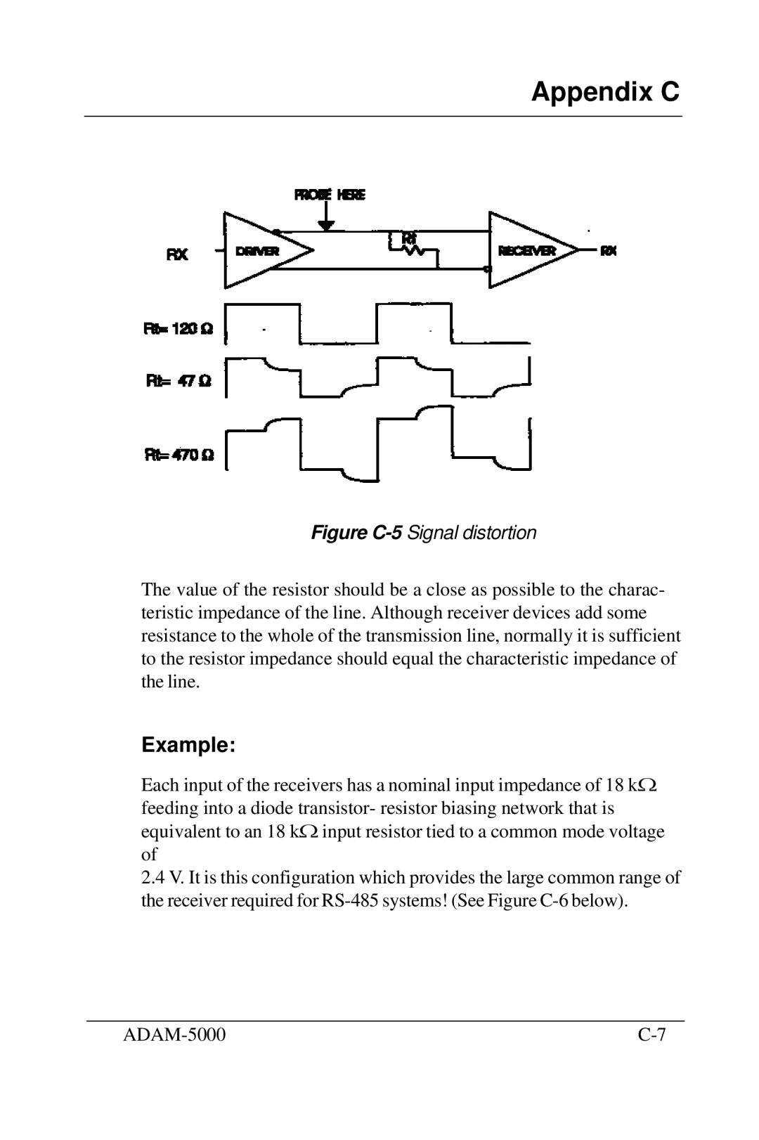
Figure C-5 Signal distortion
The value of the resistor should be a close as possible to the charac- teristic impedance of the line. Although receiver devices add some resistance to the whole of the transmission line, normally it is sufficient to the resistor impedance should equal the characteristic impedance of the line.
Example:
Each input of the receivers has a nominal input impedance of 18 kΩ feeding into a diode transistor- resistor biasing network that is equivalent to an 18 kΩ input resistor tied to a common mode voltage of
2.4V. It is this configuration which provides the large common range of the receiver required for
|