Appendix F
Single Point Grounding
|
|
|
|
|
|
|
|
|
|
|
|
|
|
|
|
|
|
|
| +24V |
|
|
|
|
|
|
|
|
|
|
| |
|
|
|
|
|
|
|
|
|
|
|
|
|
|
|
|
|
|
|
| Power |
|
+16V |
| +18V |
| +20V |
| +22 |
| Supply |
| |
|
|
|
|
|
| |||||
+22V |
| +22V |
| +22V |
| +22 |
|
|
| |
|
|
|
|
|
|
|
|
| +24 | V |
|
|
|
|
|
|
|
|
| ||
|
|
|
|
|
|
|
|
| ||
|
|
|
|
|
|
|
|
| ||
|
|
|
|
|
|
|
|
| ||
|
|
|
|
|
|
|
|
| ||
|
|
|
|
|
|
|
|
|
|
|
|
|
|
|
|
|
|
|
|
|
|
Power
Supply
More cable, but more stable system.
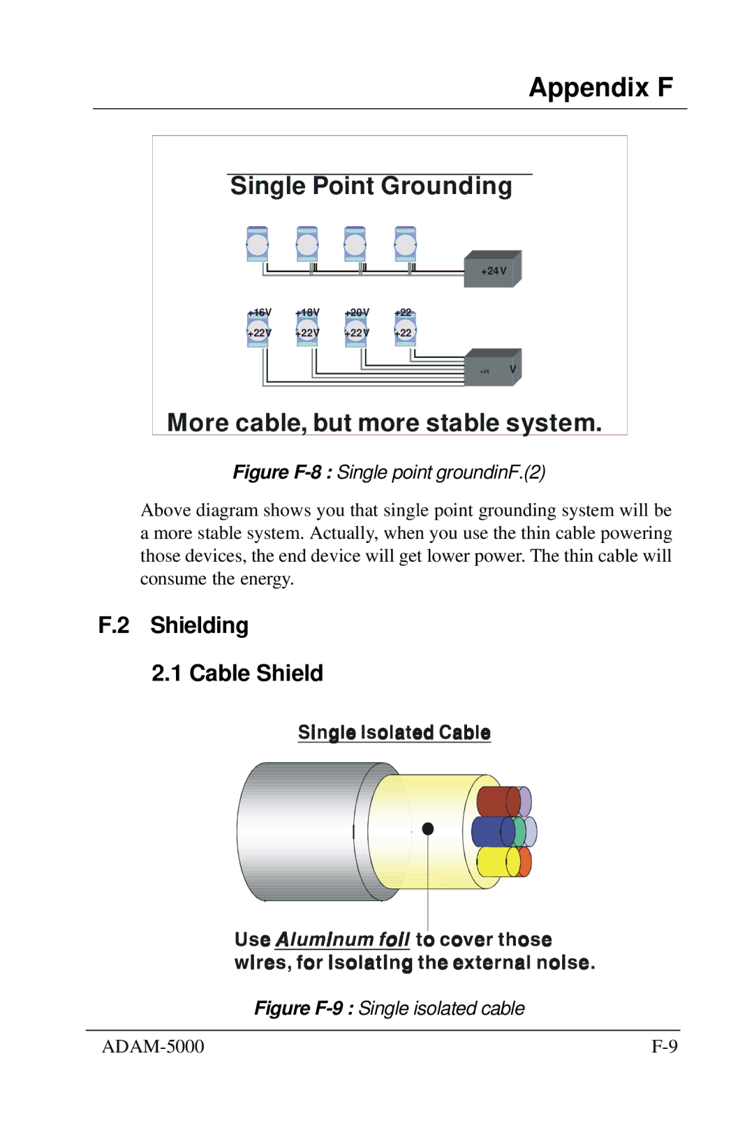
Figure F-8 : Single point groundinF.(2)
Above diagram shows you that single point grounding system will be a more stable system. Actually, when you use the thin cable powering those devices, the end device will get lower power. The thin cable will consume the energy.
F.2 Shielding
2.1 Cable Shield
Figure F-9 : Single isolated cable
|