RS-485 Network
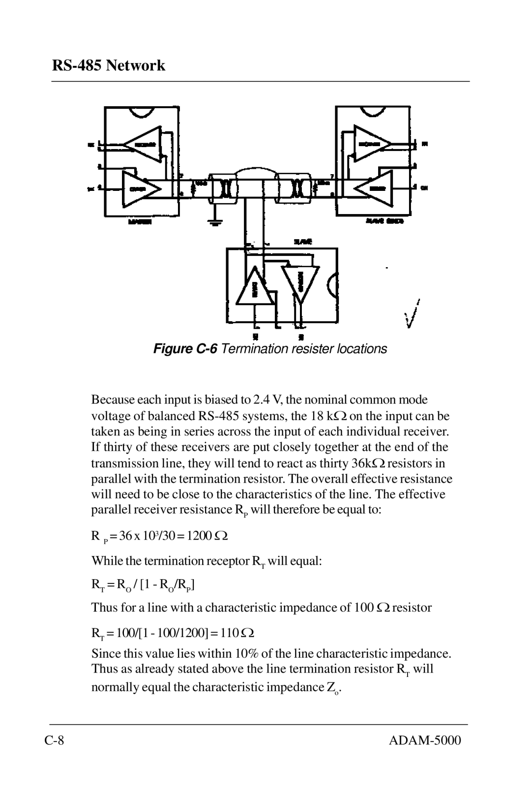
Figure C-6 Termination resister locations
Because each input is biased to 2.4 V, the nominal common mode voltage of balanced
R P = 36 x 103/30 = 1200 Ω
While the termination receptor RT will equal:
RT = RO / [1 - RO/RP]
Thus for a line with a characteristic impedance of 100 Ω resistor
RT = 100/[1 - 100/1200] = 110 Ω
Since this value lies within 10% of the line characteristic impedance. Thus as already stated above the line termination resistor RT will
normally equal the characteristic impedance Zo.
|