Appendix B - Wireless Technology
EAP Communication Overview
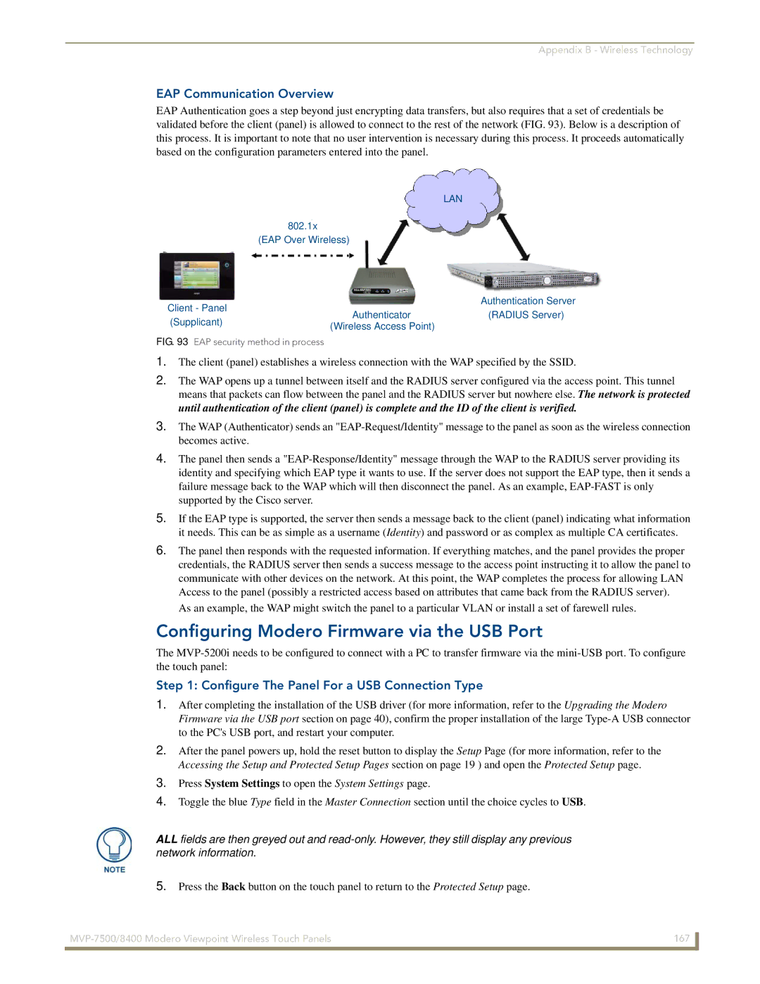
EAP Authentication goes a step beyond just encrypting data transfers, but also requires that a set of credentials be validated before the client (panel) is allowed to connect to the rest of the network (FIG. 93). Below is a description of this process. It is important to note that no user intervention is necessary during this process. It proceeds automatically based on the configuration parameters entered into the panel.
LAN
802.1x (EAP Over Wireless)
|
|
|
| Authentication Server |
| Client - Panel | Authenticator | ||
| (RADIUS Server) | |||
| (Supplicant) | |||
| (Wireless Access Point) |
| ||
|
|
|
| |
FIG. 93 EAP security method in process |
|
| ||
1.The client (panel) establishes a wireless connection with the WAP specified by the SSID.
2.The WAP opens up a tunnel between itself and the RADIUS server configured via the access point. This tunnel means that packets can flow between the panel and the RADIUS server but nowhere else. The network is protected until authentication of the client (panel) is complete and the ID of the client is verified.
3.The WAP (Authenticator) sends an
4.The panel then sends a
5.If the EAP type is supported, the server then sends a message back to the client (panel) indicating what information it needs. This can be as simple as a username (Identity) and password or as complex as multiple CA certificates.
6.The panel then responds with the requested information. If everything matches, and the panel provides the proper credentials, the RADIUS server then sends a success message to the access point instructing it to allow the panel to communicate with other devices on the network. At this point, the WAP completes the process for allowing LAN Access to the panel (possibly a restricted access based on attributes that came back from the RADIUS server).
As an example, the WAP might switch the panel to a particular VLAN or install a set of farewell rules.
Configuring Modero Firmware via the USB Port
The
Step 1: Configure The Panel For a USB Connection Type
1.After completing the installation of the USB driver (for more information, refer to the Upgrading the Modero Firmware via the USB port section on page 40), confirm the proper installation of the large
2.After the panel powers up, hold the reset button to display the Setup Page (for more information, refer to the Accessing the Setup and Protected Setup Pages section on page 19 ) and open the Protected Setup page.
3.Press System Settings to open the System Settings page.
4.Toggle the blue Type field in the Master Connection section until the choice cycles to USB.
ALL fields are then greyed out and
5.Press the Back button on the touch panel to return to the Protected Setup page.
167 | |
|
|
