Upgrading MVP Firmware
Upgrading the Modero Firmware via the USB port
Before beginning with this section, verify your panel is powered and the
the PC’s USB port. The panel must be
Establishing a USB connection between the PC and the panel, prior to installing the
USB Driver will cause a failure in the USB driver installation.
Step 1: Configure the panel for a USB Connection Type
1.After the installation of the USB driver has been completed, confirm the proper installation of the large
2.After the panel
3.Select Protected Setup > System Settings (located on the
4.Toggle the blue Type field (from the Master Connection section) until the choice cycles to USB.
ALL fields are then
5.Press the Back button on the touch panel to return to the Protected Setup page.
6.Press the
7.ONLY AFTER the unit displays the first panel page, THEN insert the
If a few minutes have gone by and the System Connection icon still does not turn green, complete the procedures in the following section to setup the Virtual Master and refresh the System from the Online Tree. This action sends out a request to the panel to respond and completes the communication (turning the System Connection icon green).
8.Navigate back to the System Settings page.
Step 2: Prepare Studio for communication via the USB port
1.Launch NetLinx Studio 2.x (default location is Start > Programs > AMX Control Disc > NetLinx Studio 2 > NetLinx Studio 2).
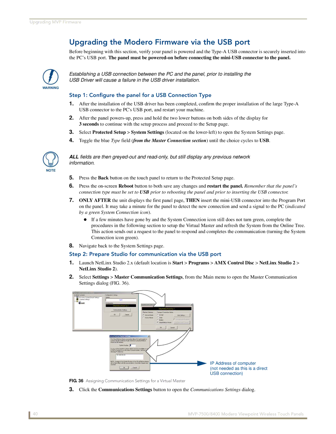
2.Select Settings > Master Communication Settings, from the Main menu to open the Master Communication Settings dialog (FIG. 36).
IP Address of computer
(not needed as this is a direct USB connection)
FIG. 36 Assigning Communication Settings for a Virtual Master
3.Click the Communications Settings button to open the Communications Settings dialog.
40 |