Upgrading MVP Firmware
4.Click on the NetLinx Master radio button (from the Platform Selection section) to indicate that you are working as a NetLinx Master.
5.Click on the Virtual Master radio box (from the Transport Connection Option section) to indicate you are wanting to configure the PC to communicate directly with a panel. Everything else such as the Authentication is
6.Click the Edit Settings button (on the Communications Settings dialog) to open the Virtual NetLinx Master Settings dialog (FIG. 36).
7.From within this dialog enter the System number (default is 1).
8.Click OK three times to close the open dialogs, save your settings, and return to the main NetLinx Studio application.
9.Click the OnLine Tree tab in the Workspace window to view the devices on the Virtual System. The default System value is one.
10.
The panel will not appear as a device below the virtual system number (in the Online Tree tab) until both the system number used in step 7 for the VNM is entered into the Master Connection section of the System Settings page and the panel is restarted.
Step 3: Confirm and Upgrade the firmware via the USB port
Use the
A
1.Verify this direct USB connection
2.With the panel already configured for USB communication and the Virtual Master setup within NetLinx Studio, its now time to verify the panel is ready to receive files.
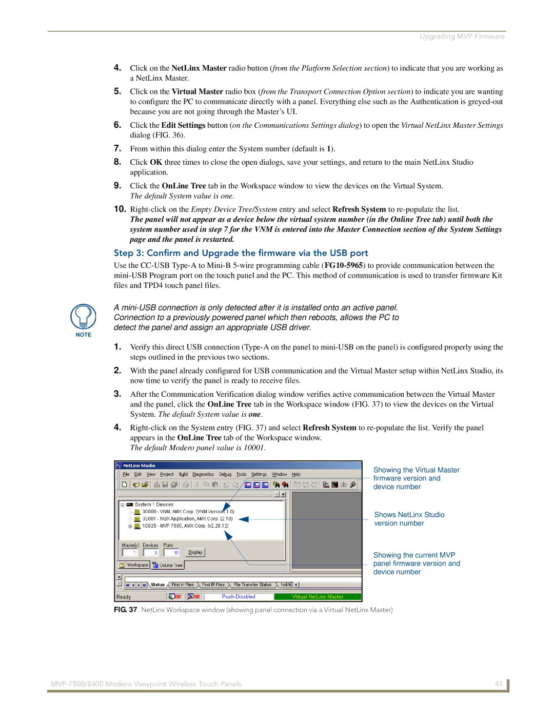
3.After the Communication Verification dialog window verifies active communication between the Virtual Master and the panel, click the OnLine Tree tab in the Workspace window (FIG. 37) to view the devices on the Virtual System. The default System value is one.
4.
The default Modero panel value is 10001.
Showing the Virtual Master firmware version and device number
Shows NetLinx Studio version number
Showing the current MVP panel firmware version and device number
FIG. 37 NetLinx Workspace window (showing panel connection via a Virtual NetLinx Master)
41 | |
|
|