22 en Installing the Pendant Arm Wall, Corner, and Mast (Pole) Mounts | AutoDome 800 Series HD PTZ Camera |
|
|
WARNING!
Ensure that you connect the outgoing power supply wires to the P107 heater connectors (HN and HL). The heater power (XF103) fuse can handle a higher amperage (3.15 A) than the camera power (XF102) fuse (2.0 A).
6.Route the 24 VAC outgoing power supply wires into the
7.Cut and trim the 24 VAC power and ground wires with sufficient slack to reach their connector terminal in the box, but not so long as to be pinched by or to obstruct closing the cover door.
8.Attach the supplied
J101
|
|
| J102 |
| XF103 |
(FUSE) | XF101 |
| P107 | HTR DOME 5 4 3 2 1 | |
P101 |
| J103 |
| XF102 | |
|
|
|
| ||
|
|
| (LED) |
| |
24V NC | 24V |
|
|
|
|
1 2 3 | P106 | P105 |
|
| |
|
|
|
| ||
|
| GND TXD RXD C+ C- | GND TXD RXD C+ C- |
|
|
![]()
![]()
![]() 6 5
6 5![]() 4 3 2 1
4 3 2 1 ![]() 6 5 4 3 2 1
6 5 4 3 2 1![]()
![]()
![]()
![]()
![]()
![]()
![]() (FUSE) (FUSE)
(FUSE) (FUSE)![]()
![]()
![]()
![]()
![]()
![]()
![]()
![]()
![]()
![]()
![]()
![]()
![]()
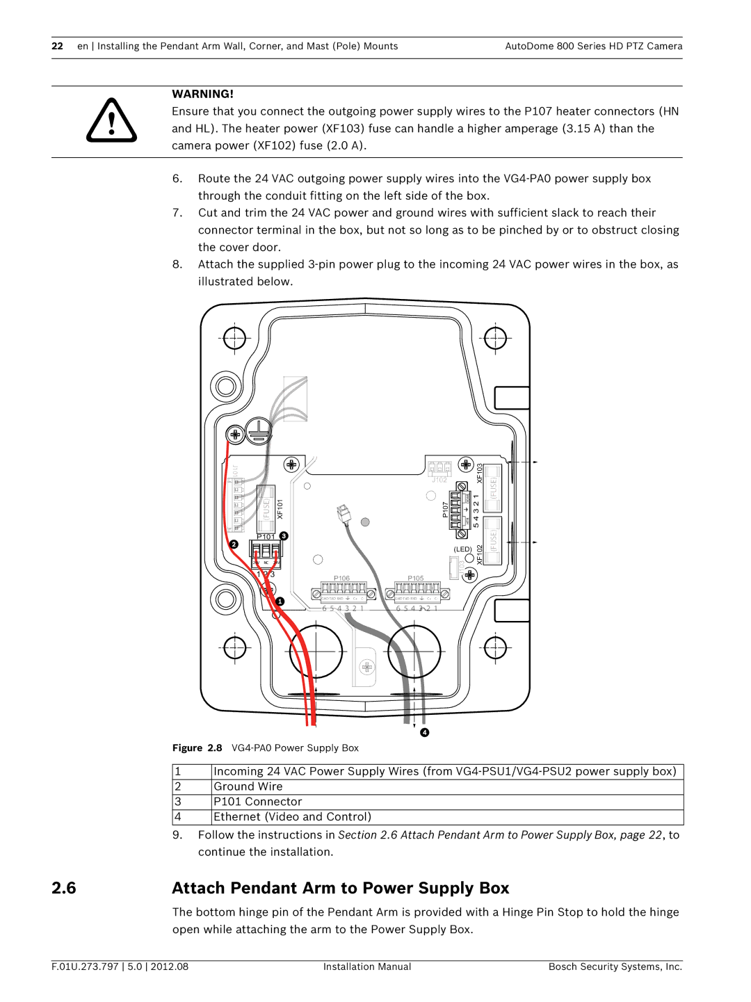
Figure 2.8 VG4-PA0 Power Supply Box
1Incoming 24 VAC Power Supply Wires (from
2 Ground Wire
3 P101 Connector
4 Ethernet (Video and Control)
9.Follow the instructions in Section 2.6 Attach Pendant Arm to Power Supply Box, page 22, to continue the installation.
2.6Attach Pendant Arm to Power Supply Box
The bottom hinge pin of the Pendant Arm is provided with a Hinge Pin Stop to hold the hinge open while attaching the arm to the Power Supply Box.
F.01U.273.797 5.0 2012.08 | Installation Manual | Bosch Security Systems, Inc. |