54 en Alarms and Relay ConnectionsAutoDome 800 Series HD PTZ Camera
5 | Alarms and Relay Connections | ||||||||||
5.1 | Alarm Inputs |
|
|
|
|
| |||||
|
| The AutoDome provides two alarm inputs. Each input can be activated by dry contact devices | |||||||||
|
| such as pressure pads, passive infrared detectors, door contacts, and similar devices. The | |||||||||
|
| table below summarizes the size and distance wires. | |||||||||
|
|
|
|
|
|
|
|
|
|
| |
|
| Wire Size | Maximum Distance |
| |||||||
|
|
|
|
|
|
|
|
|
|
| |
|
| AWG |
| mm | feet | meters |
| ||||
|
|
|
|
|
|
|
|
|
|
|
|
|
| 22 |
|
| 0.644 | 500 | 152.4 |
|
| ||
|
|
|
|
|
|
|
|
|
|
|
|
|
| 18 |
|
| 1.024 | 800 | 243.8 |
|
| ||
|
|
|
|
|
|
|
|
|
|
|
|
|
| Table 5.1 | Alarm wire guide |
|
|
|
|
| |||
|
| You wire alarms either Normally Open (N.O.) or Normally Closed (N.C.), and must program the | |||||||||
|
| alarm inputs N.O. (the default) or N.C. through the Settings page (refer to Section 7.39 Alarm | |||||||||
|
| Connections, page 95). |
|
|
|
|
| ||||
5.2 | Connecting Alarms (inputs 1 or 2) | ||||||||||
|
| You can configure alarms 1 and 2 as | |||||||||
|
| (N.C.) alarms. |
|
|
|
|
|
| |||
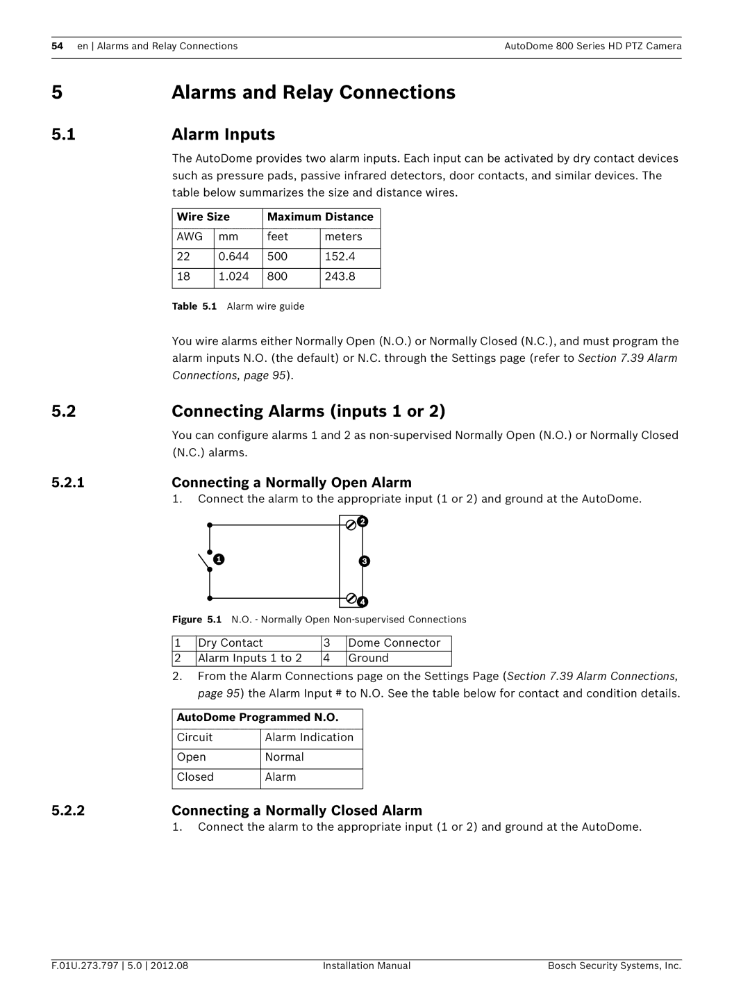
5.2.1 | Connecting a Normally Open Alarm | ||||||||||
|
| 1. Connect the alarm to the appropriate input (1 or 2) and ground at the AutoDome. | |||||||||
|
|
|
|
|
|
|
|
|
|
|
|
|
|
|
|
|
|
|
|
|
|
|
|
|
|
|
|
|
|
|
|
|
|
|
|
|
|
|
|
|
|
|
|
|
|
|
|
|
|
|
|
|
|
|
|
|
|
|
|
|
|
|
|
|
|
|
|
|
|
|
|
Figure 5.1 N.O. - Normally Open Non-supervised Connections
1 | Dry Contact | 3 | Dome Connector |
2 | Alarm Inputs 1 to 2 | 4 | Ground |
2.From the Alarm Connections page on the Settings Page (Section 7.39 Alarm Connections, page 95) the Alarm Input # to N.O. See the table below for contact and condition details.
AutoDome Programmed N.O. | |
|
|
Circuit | Alarm Indication |
|
|
Open | Normal |
|
|
Closed | Alarm |
|
|
5.2.2 | Connecting a Normally Closed Alarm |
| 1. Connect the alarm to the appropriate input (1 or 2) and ground at the AutoDome. |
F.01U.273.797 5.0 2012.08 | Installation Manual | Bosch Security Systems, Inc. |