AutoDome 800 Series HD PTZ CameraInstalling Roof Parapet and Pipe Mounts en 41
3.4.3Power Supply Box Connections
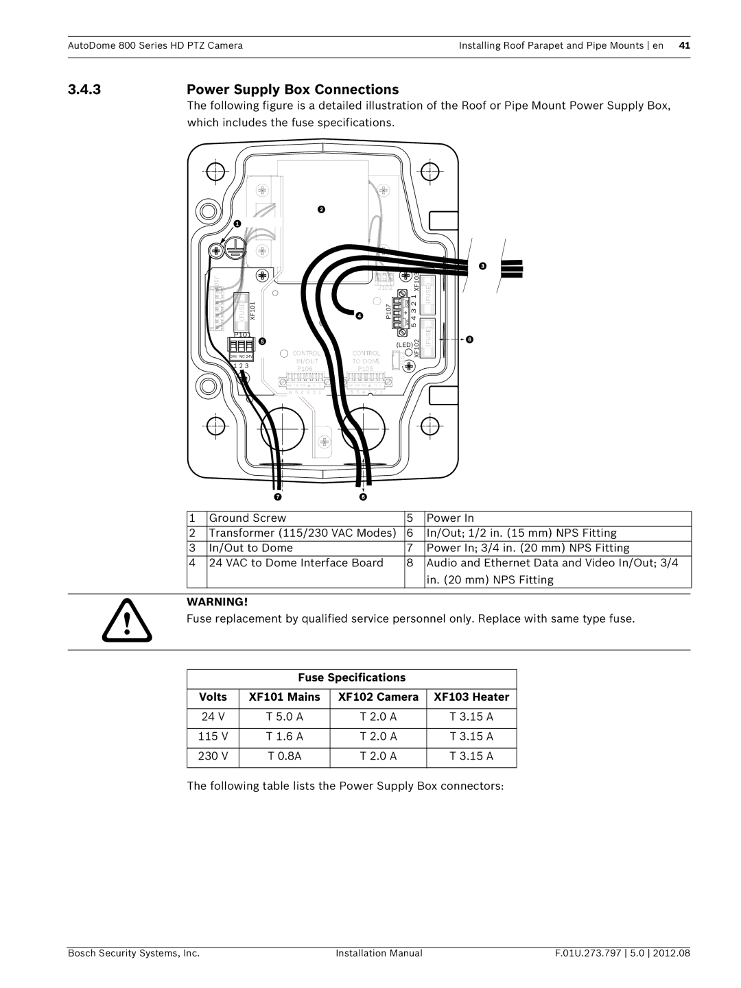
The following figure is a detailed illustration of the Roof or Pipe Mount Power Supply Box, which includes the fuse specifications.
J101 |
|
(FUSE) | XF101 |
P101 |
24V NC 24V |
1 2 3
CONTROL
IN/OUT
P106
GND T XD RXD | C+ C- |
![]() 6 5 4 3 2 1
6 5 4 3 2 1
J102 |
|
|
| XF103 |
P107 |
| HTR DOME | 5 4 3 2 1 | |
| J103 |
|
| XF102 |
| (LED) |
| ||
CONTROL |
|
|
|
|
TO DOME |
|
|
|
|
P105 |
|
|
|
|
(FUSE) (FUSE)![]()


![]()
![]()
![]()
![]()
![]()
![]()
![]()
GND T XD RXD | C+ C- |
6 5 4 3 2 1
| 1 | Ground Screw | 5 | Power In |
| 2 | Transformer (115/230 VAC Modes) | 6 | In/Out; 1/2 in. (15 mm) NPS Fitting |
| 3 | In/Out to Dome | 7 | Power In; 3/4 in. (20 mm) NPS Fitting |
| 4 | 24 VAC to Dome Interface Board | 8 | Audio and Ethernet Data and Video In/Out; 3/4 |
|
|
|
| in. (20 mm) NPS Fitting |
|
|
|
|
|
|
|
|
|
|
WARNING!
Fuse replacement by qualified service personnel only. Replace with same type fuse.
Fuse Specifications
Volts | XF101 Mains | XF102 Camera | XF103 Heater |
|
|
|
|
24 V | T 5.0 A | T 2.0 A | T 3.15 A |
|
|
|
|
115 V | T 1.6 A | T 2.0 A | T 3.15 A |
|
|
|
|
230 V | T 0.8A | T 2.0 A | T 3.15 A |
|
|
|
|
The following table lists the Power Supply Box connectors:
Bosch Security Systems, Inc. | Installation Manual | F.01U.273.797 5.0 2012.08 |