20 en Installing the Pendant Arm Wall, Corner, and Mast (Pole) Mounts |
| AutoDome 800 Series HD PTZ Camera |
| ||||||||
|
|
|
|
|
|
|
|
|
|
|
|
|
|
|
|
|
|
|
|
|
|
|
|
|
| No. |
| Connector | Pin 1 | Pin 2 | Pin 3 | Pin 4 | Pin 5 | Pin 6 |
|
|
|
|
|
|
|
|
|
|
|
|
|
|
|
|
| Ground | Grounding Screw |
|
|
|
|
| |
|
|
|
|
|
|
|
|
|
|
|
|
|
| P101 |
| 115/230 VAC or | Line | NC | Neutral |
|
|
|
|
|
|
|
| 24 VAC Power In |
|
|
|
|
|
|
|
|
|
|
|
|
|
|
|
|
|
|
|
|
| P105 |
| Data/Audio | Audio | Audio | Earth | Not Used |
|
|
|
|
|
|
|
|
|
| Ground |
|
|
|
|
|
|
|
|
|
|
|
|
|
|
|
|
|
| P106 |
| Not Used |
|
|
|
|
|
|
|
|
|
|
|
|
|
|
|
|
|
|
|
|
| P107 |
| 24 VAC Power | Dome | Dome | Earth | Heater | Heater |
|
|
|
|
|
| (Arm Harness) | 24 VAC | 24 VAC | Ground | (24 VAC) | (24 VAC) |
|
|
|
|
|
|
|
|
|
|
|
|
|
|
|
| Table 2.1 | Power Supply Box Connections |
|
|
|
|
|
| ||
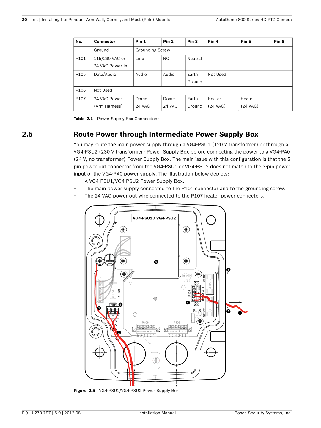
2.5 | Route Power through Intermediate Power Supply Box |
|
| ||||||||
You may route the main power supply through a
–A
–The main power supply connected to the P101 connector and to the grounding screw.
–The 24 VAC power out wire connected to the P107 heater power connectors.
VG4-PSU1 / VG4-PSU2
J101
(FUSE) | XF101 |
P101 |
|
24V NC 24V |
|
1 2 3 | P106 |
| |
| GND TXD RXD C+ C- |
![]()
![]() 6 5
6 5![]() 4 3 2 1
4 3 2 1
J102 |
| XF103 |
P107 | HTR DOME 5 4 3 2 1 | |
J103 |
| XF102 |
(LED) |
| |
P105
![]()
![]()
![]() GND TXD RXD
GND TXD RXD ![]() C+ C-
C+ C- ![]()
![]()
![]()
![]()
6 5 4 3 2 1
![]()
![]()
![]() (FUSE) (FUSE)
(FUSE) (FUSE)![]()
![]()
![]()
![]()
![]()
![]()
![]()
![]()
![]()
![]()
Figure 2.5 VG4-PSU1/VG4-PSU2 Power Supply Box
F.01U.273.797 5.0 2012.08 | Installation Manual | Bosch Security Systems, Inc. |