Chapter 5 Troubleshooting![]()
4.Store within a relative humidity range of 0% to 90% and
5.15Affecting Other Machines
An AC motor drive may affect the operation of other machines due to many reasons. Some solutions are:
High Harmonics at Power Side
High harmonics at power side during running can be improved by:
1.Separate the power system: use a transformer for AC motor drive.
2.Use a reactor at the power input terminal of the AC motor drive.
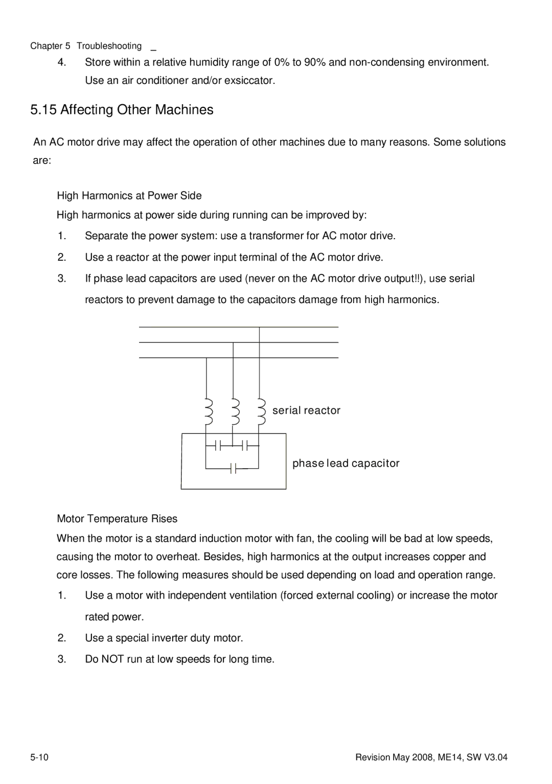
3.If phase lead capacitors are used (never on the AC motor drive output!!), use serial reactors to prevent damage to the capacitors damage from high harmonics.
serial reactor
phase lead capacitor
Motor Temperature Rises
When the motor is a standard induction motor with fan, the cooling will be bad at low speeds, causing the motor to overheat. Besides, high harmonics at the output increases copper and core losses. The following measures should be used depending on load and operation range.
1.Use a motor with independent ventilation (forced external cooling) or increase the motor rated power.
2.Use a special inverter duty motor.
3.Do NOT run at low speeds for long time.
Revision May 2008, ME14, SW V3.04 |