Chapter 2 Installation and Wiring![]()
Please use voltage and current within the regulation shown in Appendix A.
When using a GFCI (Ground Fault Circuit Interrupter), select a current sensor with sensitivity of 200mA, and not less than
Do NOT run/stop AC motor drives by turning the power ON/OFF. Run/stop AC motor drives by RUN/STOP command via control terminals or keypad. If you still need to run/stop AC drives by turning power ON/OFF, it is recommended to do so only ONCE per hour.
Do NOT connect
Output terminals for main circuit (U, V, W)
When it needs to install the filter at the output side of terminals U/T1, V/T2, W/T3 on the AC motor drive. Please use inductance filter. Do not use
DO NOT connect
Use
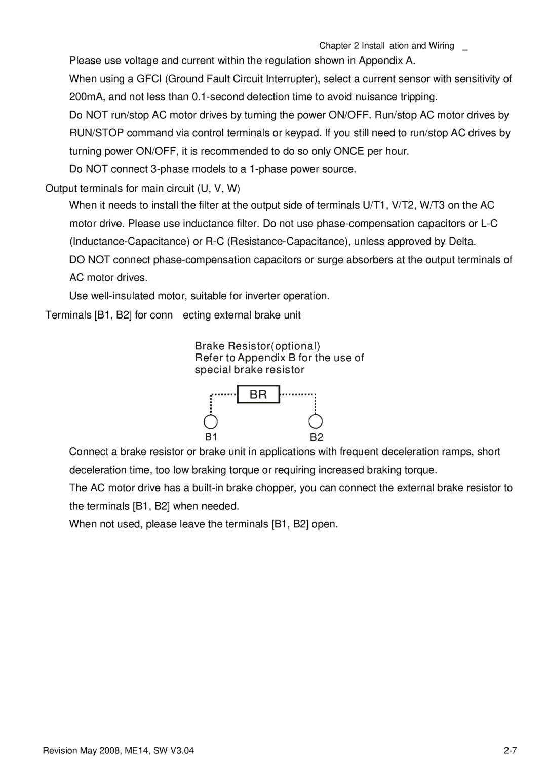
Terminals [B1, B2] for connecting external brake unit
Brake Resistor(optional)
Refer to Appendix B for the use of special brake resistor
BR
B2
Connect a brake resistor or brake unit in applications with frequent deceleration ramps, short deceleration time, too low braking torque or requiring increased braking torque.
The AC motor drive has a
When not used, please leave the terminals [B1, B2] open.
Revision May 2008, ME14, SW V3.04 |