|
| Chapter 2 Installation and Wiring | ||
Terminal | Terminal Function | Factory Settings (NPN mode) | ||
Symbol | ||||
|
|
| ||
|
| Maximum: 48Vdc, 50mA | ||
|
| Refer to P45 for programming. | ||
|
| Max: 48Vdc/50mA | ||
MO1 |
| MO1 | ||
(Photocoupler) |
| |||
|
|
| ||
|
| Internal Circuit | MCM | |
MCM | Common for | |||
(Photocoupler) | ||||
|
|
| ||
Note: Use
Analog inputs (AVI, ACI)
Analog input signals are easily affected by external noise. Use shielded wiring and keep it as short as possible (<20m) with proper grounding. If the noise is inductive, connecting the shield to terminal GND can bring improvement.
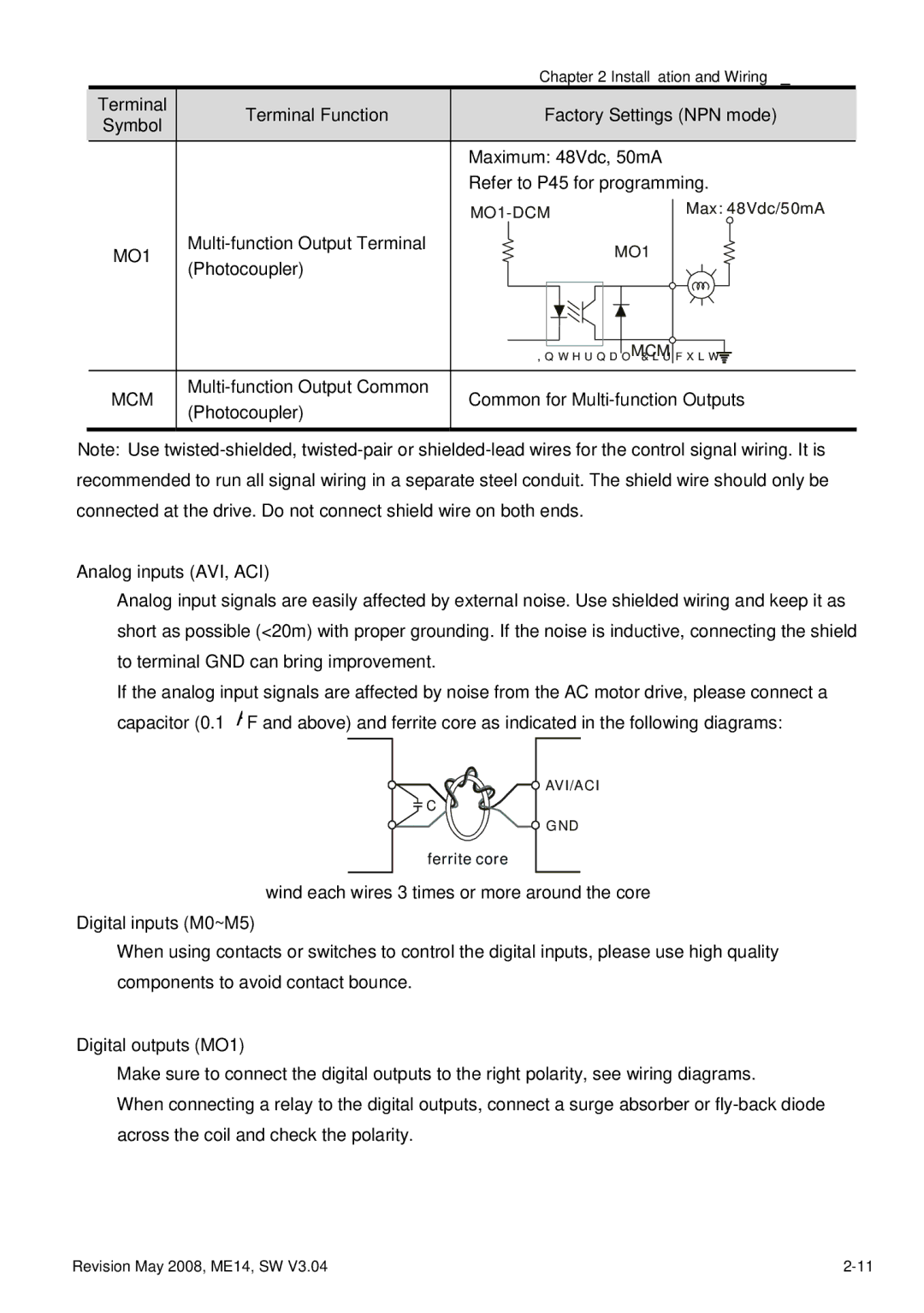
If the analog input signals are affected by noise from the AC motor drive, please connect a capacitor (0.1 μ F and above) and ferrite core as indicated in the following diagrams:
![]() AVI/ACI
AVI/ACI
![]() C
C
![]() GND
GND
ferrite core
wind each wires 3 times or more around the core Digital inputs (M0~M5)
When using contacts or switches to control the digital inputs, please use high quality components to avoid contact bounce.
Digital outputs (MO1)
Make sure to connect the digital outputs to the right polarity, see wiring diagrams.
When connecting a relay to the digital outputs, connect a surge absorber or
Revision May 2008, ME14, SW V3.04 |